


Source: Science Advances article
Upcoming advancements in flexible technology require mechanically compliant dielectric materials. Current dielectrics have either high dielectric constant, K (e.g., metal oxides) or good flexibility (e.g., polymers). Here, we achieve a golden mean of these properties and obtain a lightweight, viscoelastic, high-K dielectric material by combining two nonpolar, brittle constituents, namely, sulfur (S) and selenium (Se). This S-Se alloy retains polymer-like mechanical flexibility along with a dielectric strength (40 kV/mm) and a high dielectric constant (K = 74 at 1 MHz) similar to those of established metal oxides. Our theoretical model suggests that the principal reason is the strong dipole moment generated due to the unique structural orientation between S and Se atoms. The S-Se alloys can bridge the chasm between mechanically soft and high-K dielectric materials toward several flexible device applications.
INTRODUCTION
Dielectric materials in the form of insulators, capacitors, and resonators are important passive components in most electrical and electronic circuits used for energy storage, pulsed power, power conditioning, band-pass filtering, sensing, and microelectronics. The current “flexible” technology wave in these areas has increased the demand for flexible high-K dielectric materials.
Conventional dielectrics are either ceramics or polymers. Ceramic dielectrics are high-K brittle materials such as BaTiO3, HfO2, SiO2, and SrTiO3 with large losses and low breakdown voltage, whereas polymers such as polyvinylidene difluoride (PVDF), polyamide, and rubber have high dielectric strength and flexibility but low-K values limit their application in devices. To get the best of both polymer and ceramic dielectrics, polymer composites with various high-K ceramic nanoparticle fillers have been considered.
We eschew the composite approach in this work to develop a new monolithic, lightweight, flexible, and high-K dielectric material by combining two common nonpolar, brittle constituents, sulfur (S) and selenium (Se), through a facile scalable comelting process. S and Se are miscible in all ratios and form chalcogenide alloys whose optical and photoconduction properties have been studied in the literature (18, 19).
The comelted S-Se alloy exhibits viscoelastic behavior and mechanical flexibility like soft polymers. The dielectric constant (K = 74 at 1 MHz) and the dielectric strength (40 kV/mm) are comparable to some of the conventional metal oxides (0 < K < 80) and 10 times higher than polymers (1 < K < 10). There is a 13 times increment in the dielectric constant as compared to the individual components S and Se. Theoretical models suggest that such polarization in S-Se is the result of a strong dipole moment generated because of the unique structural and electronic interactions between S and Se. These chalcogen alloys could fill the gap for soft high-K dielectric materials in several flexible device applications.
RESULTS
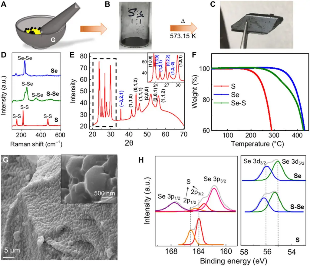
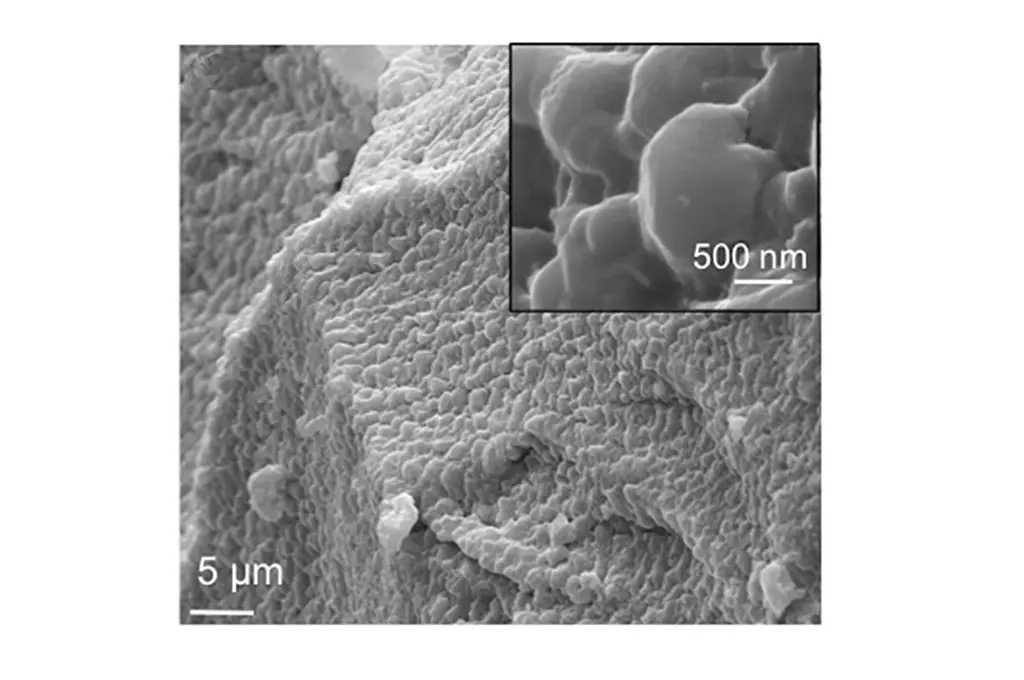
Fig. 1 Structural characterization of the S-Se alloy.(A) Schematic representing the procedure of synthesis of the S-Se alloy. S and Se are taken in a 1:1 molar ratio in a mortar and pestle. (B) Ground powder mixture of S and Se. (C) S-Se alloy obtained after comelting at 573 K. Photo credit for (C): Sandhya Susarla, Rice University. (D) Raman spectrum of the comelted pure S, S-Se alloy, and pure Se. (E) XRD of the comelted pure S, S-Se alloy, and pure Se. (F) TGA of pure S, pure Se, and S-Se alloys showing degradation at 488, 573, and 623 K, respectively. (G) SEM of the S-Se alloy showing a layered structure and the absence of voids. The inset of the high-magnification image details the size of each flake. (H) Elemental analysis of XPS spectrum of the comelted pure S, S-Se alloy, and pure Se, showing the amount of shift in the individual spin-split peak of S and Se with alloying.
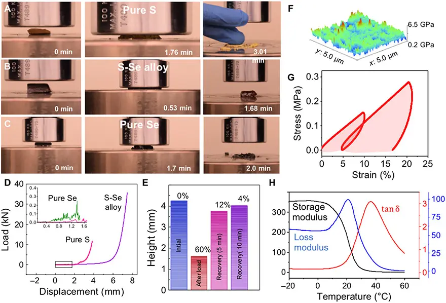
Fig. 3 Mechanical properties of S-Se alloys.Snapshots taken at different time intervals of compression test done. (A) Pure S. (B) S-Se alloy. (C) Pure Se. The S-Se alloy shows excellent recoverability. Photo credit for (A) to (C): Mohammad Sajadi and Peter Owuor, Rice University. (D) Load-displacement curves for the compression test done on the three samples. (E) Height of the sample measured at different time intervals during recovery. The strain values at those instances are also indicated above the bar column. (F) AFM modulus mapping of S-Se alloys taken over 5 μm × 5 μm area. (G) Cyclic tensile tests carried out in DMA, giving rise to hysteresis (red shaded area) in the load-unload curves, thus confirming the viscoelastic behavior. (H) Variation of storage modulus, loss modulus, and damping (tanδ) with temperature.
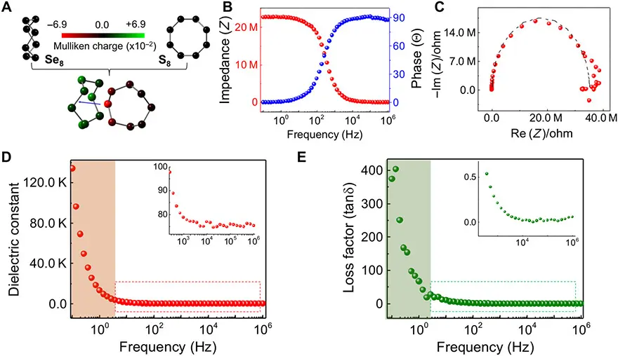
Fig. 4 Dielectric properties of S-Se alloys.(A) Se8 and S8 are initially nonpolar, zero Mulliken charge on each atom and zero net dipole moment on each molecule. However, the transverse orientation of the combination between the two molecules is a polar compound, with the highest dipole moment of all cases considered (+2.8135 D). The redder the atom, the more negative the Mulliken charge (×10−2); the greener the atom, the more positive the Mulliken charge (×10−2). Thus, the dipole moment goes from S8 to Se8 (see blue arrow). (B) Impedance (Z*) and phase versus frequency plots of S-Se alloys. (C) Nyquist plots showing the capacitive behavior of S-Se alloys. (D) Variation of dielectric constant calculated from the impedance plots in (C) with frequency. The high dielectric constant in the highlighted orange region is due to electrode polarization. The stable dielectric constant, K = 74, in the kilohertz to megahertz frequencies is shown in the inset. (E) The dielectric loss factor (tanδ) as a function of frequency indicates dielectric loss at kilohertz to megahertz frequencies. The high dielectric losses at lower frequencies (highlighted green region) are due to electrode polarization.
DISCUSSION
In summary, it is observed that surprisingly when two brittle and nonpolar chalcogen elements, S and Se, are comelted, a semicrystalline material is formed, with amorphous S-Se, monoclinic S-Se, and hexagonal Se phases. The local interaction of Se8 and S8 rings in the structure results in high polarization between S8 and Se8 and high resistance to mechanical compression due to repulsion of dipole moments between Se8 and Se8. This molecular-level repulsion in Se-Se bonds in S-Se alloys results in unique mechanical behavior including viscoelasticity with excellent mechanical recovery (96%), high Young’s modulus among polymers (3 GPa), and Tg (9.83 ± 1.14)°C, which is below the room temperature. The polar nature of the alloy results in a high dielectric constant (K = 74) at 1-MHz frequency with an extremely low dielectric loss (0.001). The dielectric strength of this alloy, 40 kV/mm, is quite high among polymer materials. This cheap, scalable, lightweight, elastic, high-K dielectric could become a valuable new dielectric material, with dielectric constant comparable to that of the high-K brittle ceramic metal oxides used in the industry and flexibility comparable to that of the low-K polymer dielectrics that are considered for emerging flexible technologies.
read full article in pdf here.
Original article published at Science Advances 10 May 2019:
Vol. 5, no. 5, eaau9785
DOI: 10.1126/sciadv.aau9785
Authors: Sandhya Susarla1, Thierry Tsafack1, Peter Samora Owuor1, Anand B. Puthirath1, Jordan A. Hachtel2, Ganguli Babu1, Amey Apte1, BenMaan I. Jawdat1, Martin S. Hilario3, Albert Lerma4, Hector A. Calderon5, Francisco C. Robles Hernandez6, David W. Tam7, Tong Li8, Andrew R. Lupini9, Juan Carlos Idrobo2, Jun Lou1, Bingqing Wei8, Pengcheng Dai7, Chandra Sekhar Tiwary1,10, and Pulickel M. Ajayan1,*
1Department of Materials Science and Nano-engineering, Rice University, Houston, TX 77005, USA.
2Center for Nanophase Materials Sciences, Oak Ridge National Laboratory, Oak Ridge, TN 37831, USA.
3Air Force Research Laboratory, Kirtland Air Force Base, Albuquerque, NM 87117, USA.
4Leidos Inc., Albuquerque, NM 87106, USA.
5Mechanical Engineering Technology, University of Houston, Houston, TX 77204, USA.
6Instituto Politécnico Nacional, ESFM, UPALM, Zacatenco, Mexico CDMX 07338, Mexico.
7Department of Physics and Astronomy, Rice University, Houston, TX 77005, USA.
8Department of Mechanical Engineering, University of Delaware, Newark, DE 19716, USA.
9Materials Science and Technology Division, Oak Ridge National Laboratory, Oak Ridge, TN 37831, USA.
10Department of Materials Science and Engineering, Indian Institute of Technology, Kharagpur-721302, India.


