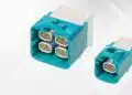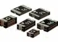
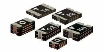


ROHM’s new UCR10C series is a sintered metal current sense chip resistor family in 2012 metric size (2.0 × 1.25 mm) that delivers up to 1.25 W rated power in low-ohmic values from 10 mΩ to 100 mΩ. The combination of high power density, low TCR and automotive‑grade robustness targets demanding current measurement in automotive, industrial and consumer designs where board space and accuracy are critical.
Key features and benefits
The UCR10C series is positioned as a high‑power, low‑ohmic shunt resistor family for current detection in compact SMD footprints.
- 2012 size (2.0 × 1.25 mm) sintered metal shunt resistors rated at 1.0 W and 1.25 W depending on value, claiming the highest power rating in this footprint as of January 2026.
- Resistance range from 10 mΩ to 100 mΩ, suitable for low‑side and high‑side current sensing in typical power stages.
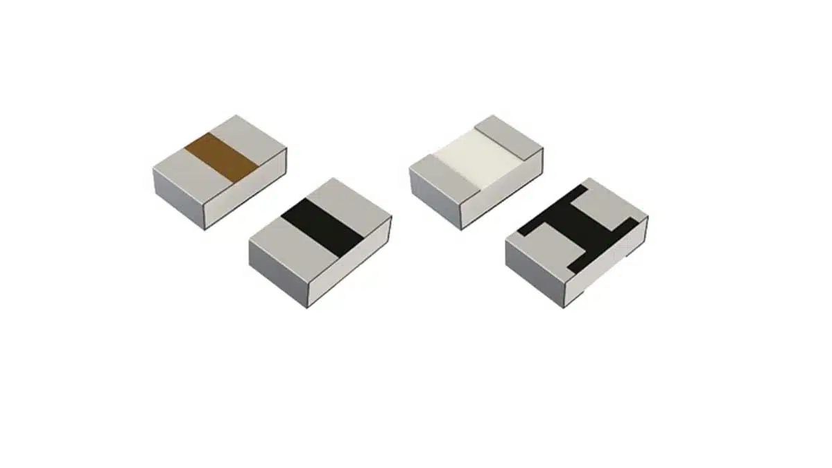
- Copper‑based resistive element formed on an alumina substrate using a sintering process, with an optimized heat dissipation structure to handle higher power than conventional thick film or metal plate shunts in the same size.
- Low TCR metal resistive element technology, with typical TCR around 0 to +60 ppm/°C (guaranteed value defined for +25 to +155 °C at 10 mΩ), which helps keep measurement error small over temperature.
- Durability in temperature cycling of −55 °C to +155 °C for 1000 cycles, on par with metal plate shunt technologies, supporting high junction and bonding reliability in harsh environments.
- Lead‑free construction with no leaded materials even in formerly RoHS‑exempt areas, supporting environmentally conscious designs.
For design engineers, the key benefit is the ability to replace larger shunt packages or wide‑terminal variants with a standard 2012 footprint while maintaining or improving power handling and measurement stability. Purchasing teams benefit from the option to consolidate to a smaller package across multiple designs without sacrificing reliability, simplifying sourcing and inventory.
Typical applications
ROHM targets the UCR10C series at current detection functions where both power dissipation and accuracy are important.
Typical use cases include:
- Automotive ECUs and power distribution, for example:
- Battery and DC‑DC converter current monitoring.
- Motor and actuator current sensing in body and chassis systems.
- On‑board charger and auxiliary inverter current measurement.
- Industrial equipment:
- Power supplies and DC bus monitoring in factory automation and robotics.
- Motor drives and servo amplifiers where shunt size and heat dissipation are constrained.
- Power management in PLCs, sensors and gateways.
- Consumer and prosumer electronics:
- High‑efficiency AC‑DC adapters, gaming and workstation PSUs.
- Battery‑powered tools and e‑mobility light vehicles where board area is limited.
In many of these designs, a 2012‑size high‑power shunt allows engineers to shrink sense resistors in crowded power stages such as primary or secondary current sense, low‑side shunts in synchronous buck converters, or phase current measurement in BLDC/PMSM drives.
Technical highlights
The main technical characteristics that matter during component selection and comparison for shunt resistors:
Package, power rating and resistance range
- Package size: 2012 metric (often referred to as 0805 inch class in many catalogues), enabling drop‑in use in standard current sense footprints where layout is already fixed.
- Rated power:
- 1.0 W and 1.25 W options within the family; rated power is specified according to the manufacturer’s datasheet for each resistance value.
- Compared to conventional thick film and metal plate shunts in the same size, these values are roughly double the rated power, allowing higher continuous current or more margin.
- Resistance range: 10 mΩ to 100 mΩ; this allows:
- Lower values (around 10–20 mΩ) for high current rails with minimal voltage drop.
- Higher values (up to 100 mΩ) for lower current sensing where ADC resolution or offset is a limitation.
Designers should refer to the manufacturer’s detailed datasheet for exact derating curves versus ambient temperature, maximum sense current per value and specific resistance options within the range.
Sintered metal structure and thermal behaviour
The UCR10C series uses a copper‑based resistive element formed on an alumina substrate by sintering and an optimized thermal path to the terminations.
- Compared with thick film chip resistors:
- Sintered metal shunts can achieve better thermal conductivity and thus higher power density in a similar footprint.
- The metal structure generally offers improved long‑term stability under load and temperature.
- Compared with metal plate wide‑terminal solutions:
- UCR10C offers comparable power handling in a smaller standard footprint, potentially eliminating the need for special wide‑terminal pad layouts.
- Thermal dissipation is improved versus conventional 2012 resistors but still depends strongly on PCB copper area and layout; designers should treat the rated power as valid only under the specified test conditions.
In practice, the higher rated power lets engineers increase measurable current, reduce self‑heating at a given current, or add safety margin against abnormal or transient loading.
TCR and temperature cycling reliability
Temperature coefficient of resistance (TCR) quantifies how much the resistance changes as temperature drifts away from the reference (typically 25 °C).
- UCR10C achieves low TCR values, around 0 to +60 ppm/°C, depending on resistance value.
- For the 10 mΩ value, the TCR specification is guaranteed over +25 to +155 °C, which is important for high‑temperature automotive and industrial environments.
- Low TCR is critical when:
- The sense resistor sets the gain of a current measurement path feeding an ADC or comparator.
- Maintaining consistent over‑current threshold and efficiency across the full operating temperature range is important.
The series is qualified for 1000 temperature cycles between −55 °C and +155 °C with performance comparable to metal plate shunts, supporting long‑term stability in systems that experience frequent cold‑start and high‑load phases, such as under‑hood ECUs or motor inverters.
Availability and part numbers
The UCR10C series is already available through major catalog distributors and ROHM’s own online distribution.
- Distribution channels listed include:
- ROHM online purchase portal, with a sample price indicated around 0.5 USD per unit (excluding tax; actual pricing depends on quantity and channel).
- DigiKey, Mouser and Farnell, which provide parametric search, stock status and purchasing options for various UCR10C values.
- Part numbering and exact ordering codes:
- Individual part numbers, resistance values and tolerance options are defined in the manufacturer’s parametric search and datasheets for UCR10C.
- Engineers should use ROHM’s current detection low‑ohmic chip resistor overview and UCR10C parametric page to select specific variants matching their resistance, tolerance and packaging needs.
ROHM is also expanding the sintered metal shunt portfolio with the 3216‑size UCR18C series rated at 2 W, offering a migration path for designs requiring even higher power handling in a slightly larger footprint.
Design‑in notes for engineers
When designing with UCR10C shunt resistors, several practical aspects can help ensure reliable measurements and robust thermal performance.
Electrical design considerations
- Sense voltage and current range:
- Calculate expected sense voltage using the chosen resistance; confirm that this is within the input range and noise floor of your ADC or amplifier and below any maximum sense voltage rating in the datasheet.
- For high currents, consider starting from low values in the 10–20 mΩ range to limit losses, then verify power dissipation against the resistor’s derating curves.
- TCR impact on accuracy:
- Estimate worst‑case current measurement error by combining TCR, tolerance and amplifier/ADC errors over the full application temperature range.
- Low TCR of UCR10C is advantageous when reducing calibration steps or trimming cost in production.
Where exact maximum current or pulse ratings are critical, consult the manufacturer’s datasheet rather than inferring from nominal power figures.
Layout and thermal management
- PCB copper area:
- UCR10C’s high rated power relies on effective heat spreading into the PCB; use sufficiently large copper areas connected to both terminals and, where possible, to inner layers or planes.
- Avoid long, narrow traces that restrict heat flow; instead, use wide copper pours and multiple vias to spread heat.
- Sense Kelvin routing:
- For high‑accuracy measurements, route separate Kelvin sense traces from the inner pads near the resistor body to the current sense amplifier, avoiding shared high‑current paths that introduce additional drops.
- Keep sense traces short and symmetrical to reduce common‑mode noise pickup.
- Thermal environment:
- In automotive ECUs or compact industrial drives, place the shunt away from the hottest power semiconductors if possible, or account for elevated local ambient when interpreting power ratings.
- Consider airflow, neighboring components and housing to ensure that the real operating temperature stays within the resistor’s limits.
Reliability and qualification aspects
- Operating temperature:
- UCR10C is designed for environments with significant temperature swings from −55 °C to +155 °C, but real application limits must follow the datasheet’s recommended operating range.
- Soldering and assembly:
- Follow ROHM’s recommended reflow profile and land pattern to achieve reliable solder joints and avoid mechanical stress on the alumina substrate.
- For harsh vibration environments, coordinate with mechanical engineers to check resonance and board fixation near the shunt.
By treating UCR10C as a high‑power, low‑TCR building block in the current measurement chain, engineers can reduce shunt size, improve accuracy and gain thermal margin compared to conventional thick film 2012 parts, while maintaining reliability equivalent to metal plate solutions.
Source
The information in this article is based on an official ROHM Semiconductor press release and associated product pages for the UCR10C and UCR18C sintered metal shunt resistor series, complemented by general application know‑how for current sense resistors. For exact electrical and environmental limits, engineers should always refer to the latest manufacturer datasheets and parametric search data.
References
- ROHM press release – Industry’s Highest Rated Power! ROHM Unveils the UCR10C Series of Sintered Metal Shunt Resistors
- ROHM UCR10C low‑ohmic current detection chip resistor parametric search
- ROHM UCR18C low‑ohmic current detection chip resistor parametric search
- ROHM online distribution search for UCR10C series