Passive Components Blog
No Result
View All Result
  • Home
  • NewsFilter
    • All
    • Aerospace & Defence
    • Antenna
    • Applications
    • Automotive
    • Capacitors
    • Circuit Protection Devices
    • electro-mechanical news
    • Filters
    • Fuses
    • Inductors
    • Industrial
    • Integrated Passives
    • inter-connect news
    • Market & Supply Chain
    • Market Insights
    • Medical
    • Modelling and Simulation
    • New Materials & Supply
    • New Technologies
    • Non-linear Passives
    • Oscillators
    • Passive Sensors News
    • Resistors
    • RF & Microwave
    • Telecommunication
    • Weekly Digest

    Nvidia Vera Rubin: Why One AI Rack Needs So Many More MLCC Capacitors

    Stackpole Introduces 1400A Busbar Shunt Resistors

    Tecate Unveils High‑temp 105C Supercapacitors for Harsh‑Environment Designs

    Bourns Expands 1000V High‑Power Fuses for Semiconductor and Battery Protection

    Passive Components in 2026: From Invisible Commodity to Design Parameter

    Bourns Introduces High Current Chip Ferrite Beads for Dense Power Rails

    Wk 22 Electronics Supply Chain Digest

    Vishay Releases High‑Current Radial Inductors up to 209 A

    May 2026 Interconnect, Passives and Electromechanical Components Market Insights

    Trending Tags

    • Ripple Current
    • RF
    • Leakage Current
    • Tantalum vs Ceramic
    • Snubber
    • Low ESR
    • Feedthrough
    • Derating
    • Dielectric Constant
    • New Products
    • Market Reports
  • VideoFilter
    • All
    • Antenna videos
    • Capacitor videos
    • Circuit Protection Video
    • Filter videos
    • Fuse videos
    • Inductor videos
    • Inter-Connect Video
    • Non-linear passives videos
    • Oscillator videos
    • Passive sensors videos
    • Resistor videos

    Current Sense Transformer Datasheet and Design‑in Guide

    Designing a USB Type‑C Flyback Planar Transformer with Frenetic’s Planar Tool

    Magnetics Design in High‑Frequency GaN Converters

    Qi2 Wireless Charging: Inductors, Capacitors and EMC Filters

    Two‑capacitor paradox explained for engineers

    Capacitances of Nonlinear MLCCs: What Datasheets Don’t Tell You

    Tapped Inductor Buck Converter Fundamentals

    Planar vs Conventional Transformer: When it Make Sense

    Modeling Fringing Field Losses in Inductors & Transformers

    Trending Tags

    • Capacitors explained
    • Inductors explained
    • Resistors explained
    • Filters explained
    • Application Video Guidelines
    • EMC
    • New Products
    • Ripple Current
    • Simulation
    • Tantalum vs Ceramic
  • Knowledge Blog
  • DossiersNew
  • Suppliers
    • Who is Who
  • PCNS
    • PCNS 2025
    • PCNS 2023
    • PCNS 2021
    • PCNS 2019
    • PCNS 2017
  • Events
No Result
View All Result
Passive Components Blog
No Result
View All Result

Samsung Introduces Ultra-High-Voltage 1500 V MLCCs for xEV Powertrains

16.4.2026
Reading Time: 9 mins read
A A

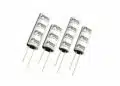
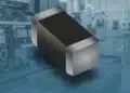
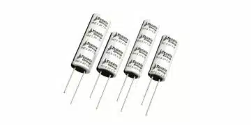
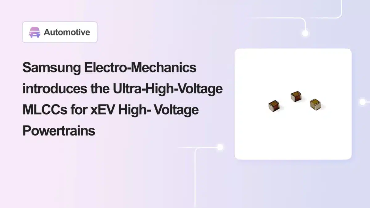
Samsung Electro-Mechanics has introduced a new range of ultra-high-voltage MLCCs in 1210 (3.2 × 2.5 mm) size for xEV high-voltage powertrains, targeting on-board chargers (OBCs) and inverter systems in modern electric vehicles.

These Samsung Electro-Mechanics MLCC capacitors combine 1000–1500 V ratings with C0G/X8G temperature characteristics and capacitance values up to 33 nF, enabling higher power density and improved reliability in compact designs.

RelatedPosts

Samsung Electro-Mechanics Signs 1.5T KRW Silicon Capacitor AI Contract

Samsung Introduced Low ESL 3-Terminal Reverse-Geometry MLCCs for High-Performance ADAS

Samsung Launches Ultra-Compact 008004 High Q MLCC for Next-Generation RF Applications

Key features and benefits

  • High voltage ratings up to 1500 V
    • Coverage across 1000 V, 1250 V and 1500 V classes supports 800 V inverter buses and high-voltage OBC topologies such as CLLC resonant converters.
  • Automotive-grade high-temperature C0G/X8G dielectrics
    • C0G parts specified from −55 °C to +125 °C with 0 ± 30 ppm/°C capacitance change offer very stable capacitance and low loss over the typical automotive ambient and under-hood range.
    • X8G parts specified from −55 °C to +150 °C with 0 ± 30 ppm/°C support use near hot power devices or in tightly packed power modules.
  • Miniaturized 1210 (3.2 × 2.5 mm) footprint
    • Provides high voltage and nF-range capacitance in a relatively small case size, enabling compact layouts in power modules and high-density OBC boards.
  • Extended capacitance range for high-voltage C0G/X8G
    • New parts expand the manufacturer’s high-voltage C0G/X8G line-up to 1.2 nF–33 nF at 1000–1500 V, bridging a gap where designers previously had to rely on film capacitors or larger MLCCs.
  • Options with fail-safe design
    • Several part numbers are offered with “Fail Safe Design” structures, intended to improve behavior under insulation breakdown and help protect the system.
  • Targeted at xEV powertrain reliability
    • Designed and mass-produced using proprietary ceramic, electrode miniaturization and ultra-precise layering processes to address the growing MLCC count and reliability requirements in electrified vehicles.
  • Support for custom designs
    • The manufacturer explicitly offers technical support and samples for customer-specific designs, which can be useful for platform-level automotive projects.

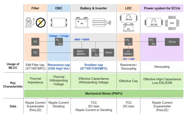
Typical applications

These ultra-high-voltage MLCCs are aimed at xEV high-voltage domains and can replace or complement film capacitors in certain functions where size reduction and board-level integration are beneficial.

Typical functions include:

  • CLLC resonant tanks in on-board chargers (OBCs)
    • Used as resonant capacitors in high-frequency CLLC stages of next-generation OBCs with output power above 22 kW, where high voltage rating and low-loss dielectric are critical for efficiency and thermal performance.
  • 800 V-class traction inverter systems
    • Deployed around inverter power modules for snubber networks and local decoupling on DC-link and half-bridge nodes.
  • Snubber capacitors for fast switching devices
    • Used to suppress switching noise and voltage overshoot when SiC or fast IGBT switches are turned on or off by providing a controlled, low-inductance path for transient energy.
  • General high-voltage nodes in xEV powertrains
    • Applicable anywhere a compact, stable, high-voltage capacitor is required, such as high-voltage measurement conditioning, auxiliary DC–DC stages, or EMI-optimized layouts in the HV domain.

Because these devices are ceramic MLCCs with C0G/X8G characteristics, they are best suited for positions where low loss, stable capacitance and predictable temperature behavior are more important than very high bulk capacitance.

Technical highlights

The current line-up described in the press release focuses on four 1210-case MLCCs with specific capacitance and voltage combinations. These parts together extend the C0G/X8G MLCC portfolio to cover 1000–1500 V with capacitances from 1.2 nF up to 33 nF in a 1210 case size.

Product overview table

Part numberSize (inch/mm)CapacitanceRated voltageTCCDesign type
CL32G122KVV3PN#1210 / 3.2×2.51.2 nF1500 VX8GFail Safe Design
CL32C103JXV3PN#1210 / 3.2×2.510 nF1250 VC0GFail Safe Design
CL32C223JIV3PN#1210 / 3.2×2.522 nF1000 VC0GFail Safe Design
CL32C333JIV1PN#1210 / 3.2×2.533 nF1000 VC0GNormal Design

Design-in notes for engineers

When designing these ultra-high-voltage MLCCs into xEV systems, a few practical considerations can help avoid issues and get the most benefit from their capabilities.

Electrical and thermal considerations

  • Respect voltage derating practices
    • Even though the parts are rated up to 1000–1500 V, it is common in automotive power designs to operate MLCCs with a margin below the maximum rated voltage, especially in applications with repetitive transients or high dv/dt.
  • Consider AC ripple and resonant conditions
    • In CLLC resonant converters, the capacitor experiences AC voltage and current superimposed on a DC offset. Check ripple current limits and loss behavior in the datasheet to ensure the MLCC does not overheat in steady-state operation.
  • Check capacitance stability over temperature and bias
    • The C0G/X8G characteristics mean temperature-related capacitance drift is very small, which is ideal for stable resonant frequencies. Any DC bias dependency at these voltage levels should be verified in the datasheet graphs.
  • Pay attention to thermal environment
    • In inverter power modules or OBC primary stages, local temperatures can approach the upper limit of X8G parts. Use thermal simulation or measurement to ensure junction and case temperatures stay within specified limits.

Layout and mechanical integration

  • Minimize ESL and loop area
    • For snubber applications, place the MLCC as close as possible to the switch terminals or module pins, with short, wide traces to minimize parasitic inductance and maximize the effectiveness of overvoltage suppression.
  • Combine multiple capacitors if needed
    • To achieve specific snubber or resonant values or to distribute current, consider using multiple MLCCs in parallel, observing spacing rules for high-voltage clearance and creepage.
  • Manage mechanical stress
    • Large ceramic capacitors in 1210 size can be susceptible to board flex cracking. Use proper pad design, controlled solder fillets and PCB support to reduce mechanical stress during assembly and vehicle operation.
  • Check fail-safe versus normal design
    • Where insulation integrity is safety-critical (for example, at the isolation barrier in OBCs), verify whether a Fail Safe Design version is available with the required capacitance and voltage, and review the datasheet description of its behavior under fault conditions.

Qualification and documentation

  • Verify automotive qualification status
    • For serial production in xEV platforms, confirm the appropriate automotive qualification standard (e.g. AEC-Q200 or manufacturer-specific testing) in the datasheet or via the manufacturer’s support channels.
  • Align with system-level standards
    • High-voltage components in OBC and inverter systems often need to comply with standards such as ISO/IEC high-voltage safety and insulation requirements. Ensure the MLCC’s rated voltage, test conditions and insulation properties align with the system-level design rules.
  • Leverage manufacturer support
    • Since Samsung Electro-Mechanics offers technical support and samples for customer-specific designs, design teams can engage early for modeling data, SPICE models, reliability data and lifetime estimations that may not be fully detailed in the press release.

Source

This article is based on information provided in the Samsung Electro-Mechanics product news release describing ultra-high-voltage MLCCs for xEV high-voltage powertrains, complemented by the associated product and datasheet links on the manufacturer’s website.

References

  1. Samsung Electro-Mechanics product news: Ultra-High-Voltage MLCCs for xEV High-Voltage Powertrains
  2. Samsung Electro-Mechanics product page – CL32G122KVV3PN#
  3. Samsung Electro-Mechanics product page – CL32C103JXV3PN#
  4. Samsung Electro-Mechanics product page – CL32C223JIV3PN#
  5. Samsung Electro-Mechanics product page – CL32C333JIV1PN#

Related

Recent Posts

Nvidia Vera Rubin: Why One AI Rack Needs So Many More MLCC Capacitors

2.6.2026
37

Stackpole Introduces 1400A Busbar Shunt Resistors

2.6.2026
9

Tecate Unveils High‑temp 105C Supercapacitors for Harsh‑Environment Designs

2.6.2026
8

Bourns Expands 1000V High‑Power Fuses for Semiconductor and Battery Protection

2.6.2026
6

Passive Components in 2026: From Invisible Commodity to Design Parameter

2.6.2026
20

Bourns Introduces High Current Chip Ferrite Beads for Dense Power Rails

1.6.2026
10

Vishay Releases High‑Current Radial Inductors up to 209 A

29.5.2026
22

May 2026 Interconnect, Passives and Electromechanical Components Market Insights

29.5.2026
92

Passive Components Enable Safe and Reliable ADAS Architectures

28.5.2026
67

Upcoming Events

Jun 16
16:00 - 17:00 CEST

EMC with EMC – EMC‑compliant design with electromechanical connectors

View Calendar

Popular Posts

  • Buck Converter Design and Calculation

    0 shares
    Share 0 Tweet 0
  • Boost Converter Design and Calculation

    0 shares
    Share 0 Tweet 0
  • Flyback Converter Design and Calculation

    0 shares
    Share 0 Tweet 0
  • MLCC and Ceramic Capacitors

    0 shares
    Share 0 Tweet 0
  • LLC Resonant Converter Design and Calculation

    0 shares
    Share 0 Tweet 0
  • Capacitor Charging and Discharging

    0 shares
    Share 0 Tweet 0
  • What Electronics Engineer Needs to Know About Passive Low Pass Filters

    0 shares
    Share 0 Tweet 0
  • Dual Active Bridge (DAB) Topology

    0 shares
    Share 0 Tweet 0
  • Ripple Current and its Effects on the Performance of Capacitors

    3 shares
    Share 3 Tweet 0
  • SEPIC Converter Design and Calculation

    0 shares
    Share 0 Tweet 0

Newsletter Subscription


Passive Components Blog

© EPCI - Leading Passive Components Educational and Information Site

  • Home
  • Privacy Policy
  • EPCI Membership & Advertisement
  • About

No Result
View All Result
  • Home
  • Knowledge Blog
  • Dossiers
  • PCNS

© EPCI - Leading Passive Components Educational and Information Site

This website uses cookies. By continuing to use this website you are giving consent to cookies being used. Visit our Privacy and Cookie Policy.
Go to mobile version