


Decoupling capacitors do more than just prevent voltage drops and pulse peaks on the supply lines from reaching the circuit in the application and limiting its functionality. When the correct capacitors are selected, they can also reduce costs, required space, and idle state power consumption. This article published by Rutronik in collaboration with KEMET explains tantalum polymer capacitors benefits in decoupling applications.
There are several reasons that speak in favour of using decoupling capacitors: They are connected to the supply pin on the IC, where they eliminate high-frequency noise before it negatively impacts or influences functionality of the ICs. Further, they smooth out any high-frequency voltage peaks caused by switching regulators. Voltage and current ripple of DC/DC converters are somewhat of a general problem, especially in applications like sensor measurement technology.
Furthermore, the decoupling capacitor acts as a local power storage system. It supplies the IC with the required amount of power during short power outage or decoupling windows (typically in the µs range) or during the switching intervals of a switched-mode power supply.
Roughly 30 to 80%, sometimes even more, of a bill of materials is made up of decoupling capacitors. The exact amount depends on the type and requirements of the active ICs used on the printed circuit board, the shape and size of the input power, and the EMC requirements on noise immunity and emissions. Selection of the correct decoupling capacitors can therefore help to significantly reduce costs, required space, and idle state power consumption. So, it is crucial to consider things carefully when choosing decoupling capacitors.
Advantages and Disadvantages of Typical Decoupling Capacitors
The designs considered below are mainly intended for analog, digital, or mixed-signal systems supplied with voltages of 50 V or less. This voltage level is usually converted down to 1 V, 1.3 V, 1.8 V, 3.3 V, 5 V, 10 V, or 12 V.
Decoupling with capacitances up to 10 µF: For voltages up to 50 V and capacitances up to 330 nF, C0G-based multilayer ceramic capacitors (MLCCs) are the best currently available technology in terms of space required, cost efficiency, and leakage current characteristics.
X7R/X5R-based MLCCs are the capacitors of choice for capacitances up to 10 µF. In this case, however, the DC bias behavior must be taken into account to ensure the required capacitance at the actual application voltage.
Tantalum capacitors or aluminum polymer capacitors can be used in the 5 µF to 10 µF range. However, they usually have higher leakage currents and are more expensive and larger – the smallest one from KEMET is an 0805 (2,012 in mm).
For example, buffer capacitance in the 8 µF to 10 µF range at 5 V can be achieved using an X7R-based MLCC with 10 µF (8.2 µF at 5 V DC bias), 10 V, 1206, e.g. C1206C106K8RACTU from KEMET, or a tantalum polymer capacitor with 15 µF, 6.3 V (with voltage derating), 3528 (comparable design ~1210 MLCC), e.g. T520T156M006ATE100 from KEMET.
X7R, however, offers advantages due to its smaller dimensions, lower price, lesser leakage current, and higher ripple current strength – a factor of almost six at 100 kHz.
Decoupling with capacitances above 10 µF: When it comes to decoupling large capacitances (> 10 µF, VDC < 50 V), either X7R/X5R MLCC banks, electrolytic capacitor/capacitor banks, or polyester or polypropylene-based film capacitors are traditionally used. But there are a few things that need to be borne in mind.
X7R/X5R MLCC banks with high nominal voltages are used to compensate for the DC bias effect. This involves connecting a number of capacitors in parallel, which is both expensive and space-consuming. The amount of space required increases additionally with the necessary decoupling capacity. Further, the leakage current increases, and its practical determination for the overall design becomes decidedly more complex.
Additional compensation is required to meet the high-capacitance requirements at high temperatures. As such, a combination of varying capacitor technologies connected in parallel is usually recommended, on the one hand, for filtering higher frequencies and, on the other hand, for filtering low interference, such as 50/60 Hz hum or vibrations in the single-digit Hz range. At the same time, there is a high risk of cracking if X7R capacitors are exposed to excessive mechanical vibrations.
Electrolytic capacitors or electrolytic capacitor banks generally have a higher ripple current strength. That said, they are often oversized to accommodate for this gain. This is necessary to compensate for or reduce higher equivalent series resistance (ESR). Since ESR increases over a capacitor’s service life, the capacitor is additionally oversized to avoid any problems in this respect. It obviously also leads to an increase in the amount of space required and costs.
Compared to MLCCs, electrolytic capacitors have a high leakage current. The capacitance drop with frequency may cause problems in effectively filtering a wide range of frequencies. To cover all frequencies, it is often necessary to have another MLCC connected in parallel. THT (through hole technology) electrolytic capacitors are commonly applied, which in turn leads to challenges associated with equipping.
Polyester or polypropylene-based film capacitors are not susceptible to cracking or high leakage currents and offer a higher ripple current capability. Film capacitors that achieve the same capacitance/nominal voltage as MLCCs or electrolytic capacitors are comparatively large and expensive.
Reducing Costs and Space Required with Tantalum Polymer Capacitors
Tantalum polymer capacitors combine many advantages that the aforesaid technologies are unable to fully achieve. It starts with the material used: Unlike conventional tantalum capacitors, MnO2 is replaced by an electrically conductive polymer. In the event of reverse polarity or a short circuit, there is, therefore, no risk of fire.
Further, in contrast to MLCCs, they also have no DC bias effect. As such, a capacitor bank is not required to compensate for voltage-dependent losses in capacitance. The capacitance of tantalum polymer capacitors is additionally not temperature-dependent, and there is no risk of cracking or hum noises with these capacitors.
Yet another advantage is their higher ripple current capability compared to electrolytic capacitors. Moreover, their capacitance drop is not as significant at high frequencies, resulting in better high-frequency capability. The leakage current is also lower in some cases than with electrolytic capacitors.
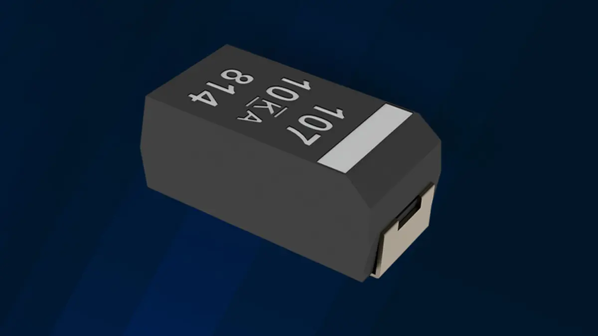
Further, tantalum polymer capacitors are not subject to aging effects and the ESR remains constant throughout their service life. A high capacitance-to-volume ratio enables compact SMD designs from 0805 to 7343.
The Table 1. below shows the various types of capacitors with the parameters needed to meet the requirements of a brushless DC motor (BLDC) module with a minimum of 30 µF at 16 V, a total ripple current of approximately 10 A at 10 kHz, a leakage current below 100 µA, and a temperature of up to 105 °C.

It can be seen from the table that the use of tantalum polymer capacitors can free up a lot of space and costs compared to MLCC or electrolytic capacitors. Added to this are a longer service life, a better high-frequency response, and a compact SMD package.
Aluminum or Tantalum Polymer Capacitors
Alongside tantalum polymer capacitors, aluminum polymer capacitors are also becoming increasingly popular. At an operating voltage below 10 V and a temperature of less than 105 °C, the response of the two polymer capacitors is very similar. However, if these values are exceeded, tantalum polymer capacitors operate more reliably.
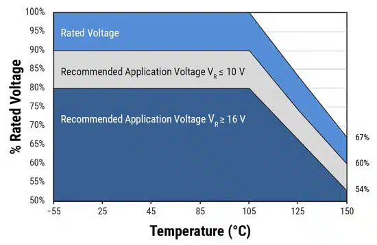
Despite offering a range of advantages, there are also certain disadvantages. At present, they are only available with a nominal voltage of up to 100 V. A voltage derated by at least 10% is recommended for temperatures up to 105 °C, and even higher for greater temperatures (Figure 1.).
Since it is a polarized capacitor, a reverse polarity protection diode should be used to protect against reverse polarities. The leakage current is higher compared to an MLCC or a conventional tantalum capacitor. Further, special attention has to be paid to the specified humidity at high temperatures to avoid any problems caused by excessive THB (temperature humidity bias) conditions.
Decoupling Large Capacities in Safety-Critical Applications
Tantalum polymer capacitors are used whenever large capacitance decoupling is required for all types of control boards and embedded electronics. Their compact, low-profile SMD design makes them an ideal link between small-capacitance MLCCs and large-capacitance electrolytic and film capacitors, which are usually used as DC link capacitors for high voltages and large power requirements.
A great many tantalum polymer capacitors are validated and approved for use on both sides of a DC/DC converter within a vehicle. This has led to their widespread adoption among major car manufacturers. In small drive systems, they can also be applied as DC link capacitors, as shown in the BLDC example above.


