
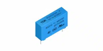




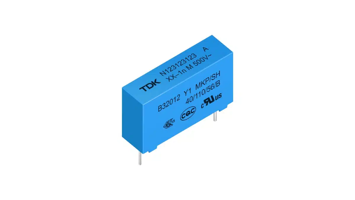
TDK has introduced the B3201*A5/B5/C5 series of metallized polypropylene Y1 safety capacitors for line-to-ground EMI suppression in automotive and industrial power electronics.
The film capacitor family combines 500 V AC and 1500 V DC ratings up to +110 °C with capacitances from 0.47 nF to 33 nF. Operation extends to +125 °C with voltage derating and a time limit, making the capacitor’s thermal operating point a central selection criterion.
Key features and benefits
- Y1 classification for line-to-ground safety-capacitor applications.
- Metallized polypropylene film construction with self-healing properties.
- Capacitance tolerances of ±10% or ±20%, depending on the ordering variant.
- Through-hole mounting with 15 mm or 22.5 mm lead spacing.
- AEC-Q200 Rev. E compliance.
- Temperature-humidity-bias testing at +85 °C, 85% relative humidity and 500 V AC for 500 hours.
- Plastic case and epoxy resin sealing meeting UL 94 V-0 requirements.
- Bulk, ammo-pack and reel delivery formats, depending on the selected type.
Technical highlights
Electrical ratings and temperature derating
| Parameter | Value | Conditions |
|---|---|---|
| Rated AC voltage | 500 V AC | 50/60 Hz; up to +110 °C |
| Rated DC voltage | 1500 V DC | Up to +110 °C |
| Maximum operating temperature | +125 °C | With voltage derating |
| Voltage derating above +110 °C | 1.5% per °C | AC and DC ratings |
| Operation above +110 °C | ≤1000 hours | Derated voltage |
| Capacitance tolerance | ±10% or ±20% | Variant-dependent |
| Dissipation factor | ≤0.002 | 1 kHz; +20 °C |
Derating applies to the capacitor’s operating temperature, which includes ambient temperature and self-heating. A surrounding air temperature below +110 °C therefore does not, by itself, establish that full rated voltage is permissible.
The +125 °C maximum is a time-limited operating condition rather than an unrestricted continuous-temperature rating. Designs with extended hot operation need to account for both the voltage reduction and the 1000-hour limit above +110 °C.
Capacitance and package selection
The film safety capacitor family comprises B32012 and B32013 types. Body size varies with capacitance and ordering variant; lead spacing alone does not define the required board area or enclosure clearance.
| Type family | Capacitance range | Lead spacing | Maximum body dimensions across variants, W × H × L |
|---|---|---|---|
| B32012A5/B5/C5 | 0.47–10 nF | 15 mm | 5.0 × 10.5 × 18.0 to 11.0 × 18.5 × 18.0 mm |
| B32013A5/B5/C5 | 5.6–33 nF | 22.5 mm | 6.0 × 15.0 × 26.5 to 14.0 × 23.5 × 26.5 mm |
Both families use parallel wire leads with a diameter of 0.8 ±0.05 mm. Lead-spacing tolerance is ±0.4 mm.
The 0.47 nF, 0.68 nF, 1.0 nF and 1.5 nF B32012 variants share a maximum body size of 5.0 × 10.5 × 18.0 mm. At higher capacitances, the selected value and tolerance variant should be fixed before allocating the final mechanical envelope.
Humidity testing and safety approvals
The 500-hour temperature-humidity-bias test combines +85 ±2 °C, 85 ±2% relative humidity and 500 V AC at 50 Hz. Post-test acceptance limits include:
- Capacitance change no greater than 10%.
- Dissipation-factor change no greater than 0.01 at 1 kHz.
- Insulation resistance of at least 0.2 GΩ.
These are acceptance limits after a defined environmental test, not an application lifetime rating.
Safety approvals cover EN IEC 60384-14:2023, UL 60384-14:2025, CSA E60384-14 and GB/T 6346.14-2023. Certification marks include ENEC, UL, CSA and CQC.
Typical applications
The series targets line-to-ground EMI filtering in:
- xEV power electronics and on-board chargers.
- EV charging infrastructure.
- Industrial drives and frequency converters.
- Telecom, datacom and server power supplies.
- Solar PV inverters and renewable-energy systems.
- Uninterruptible power supplies and energy storage systems.
The Y1 classification establishes the intended safety-filter position. The 500 V AC and 1500 V DC ratings govern voltage selection, while AEC-Q200 Rev. E compliance is relevant to automotive component qualification. The elevated-temperature limits and biased-humidity test conditions are particularly important when evaluating enclosed power-conversion equipment exposed to heat and moisture.
Design-in notes for engineers
- Check AC or DC operating voltage together with the capacitor temperature, including self-heating. Apply the temperature derating and exposure-time limit above +110 °C.
- Assess non-sinusoidal voltage stress separately from the mains-frequency voltage rating. Maximum isolated-pulse voltage-rise capability is 3000 V/µs for 15 mm lead spacing and 1000 V/µs for 22.5 mm lead spacing.
- For repetitive pulses, use the permissible AC current-versus-frequency curves. The isolated-pulse limits assume that heat from one pulse dissipates before the next pulse.
- Match PCB hole spacing to the selected lead spacing and avoid mechanical stress on the terminals.
- Plan a through-hole soldering process rather than reflow. During preheating, MKP body temperature must remain at or below +110 °C; during soldering, body temperature must remain at or below +120 °C, with exposure limited to 45 seconds.
- Validate final selection under the actual electrical, thermal, mechanical and assembly conditions before production release.
Further reading
- 12 Things You Need to Know About Preventing Overloads with Safety Capacitors
- Soldering, PCB Handling and Rework Component Guidelines
Source
This article is based on the TDK product announcement and official product documentation. Engineers should refer to the current manufacturer datasheet for final design and qualification.
References
- Film Capacitors — EMI Suppression Capacitors — B3201A5/B5/C5, TDK Electronics, May 2026.
- TDK introduces compact Y1 safety capacitors for operations up to 500 V (AC) and +125 °C, TDK Electronics, October 21, 2026.