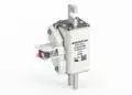

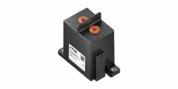



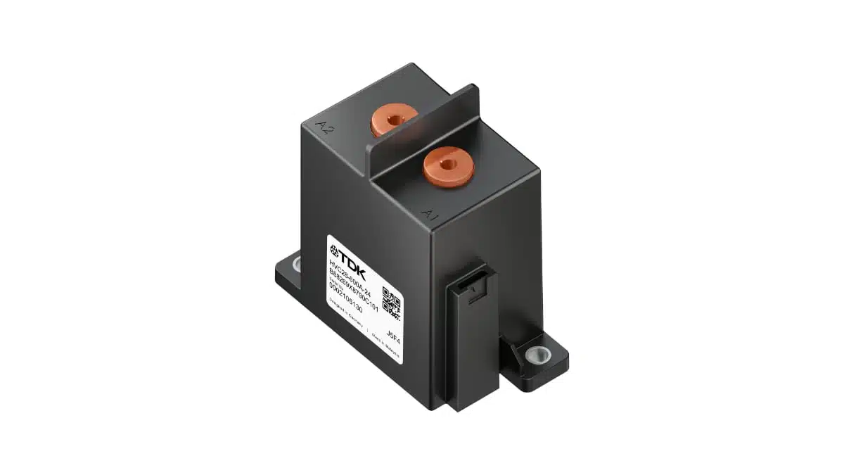
TDK has introduced the HVC28 and HVC29 series of gas-filled high-voltage DC contactors, with continuous-current versions from 300 A to 600 A.
The HVC28 supports operating voltages up to 1000 V DC, while the HVC29 extends to 1500 V DC for industrial power systems. Both families provide bidirectional main connections and an optional mechanically linked auxiliary contact for switching-state monitoring.
Key features and benefits
- Continuous-current options of 300 A, 400 A, 500 A and 600 A in each series.
- Maximum operating voltage of 1000 V DC for HVC28 and 1500 V DC for HVC29.
- Short-circuit current handling capability of 16 kA for 5 ms for HVC28 and 6 kA for 5 ms for HVC29.
- Gas-filled ceramic arc chamber for DC current interruption.
- Polarity-free main terminals supporting charging and discharging through the same contactor.
- Optional normally closed mirror contact complying with IEC 60947-4-1.
- Single-coil actuation with 12 V DC or 24 V DC control voltage and 6 W nominal coil power.
- Operating temperature range of −40 °C to +85 °C.
Technical highlights
Current carrying and current interruption are different ratings
The principal selection distinction is between carrying current continuously and interrupting it under load. The 300 A to 600 A versions define the continuous-current capability; switching endurance depends on the voltage, current and load characteristics at contact opening.
| Parameter | HVC28 | HVC29 |
|---|---|---|
| Maximum operating voltage | 1000 V DC | 1500 V DC |
| Continuous-current options | 300 / 400 / 500 / 600 A | 300 / 400 / 500 / 600 A |
| Short-circuit handling, 5 ms | 16 kA | 6 kA |
| Rated operational voltage | 1000 V DC | 1500 V DC |
| Rated operational current | 120 A DC | 75 A DC |
| Contact resistance at 100 A DC, typical / maximum | 0.15 / 0.30 mΩ | 0.15 / 0.30 mΩ |
| Make / break time | ≤40 / ≤15 ms | ≤40 / ≤15 ms |
| Rated impulse withstand voltage | 8 kV | 8 kV |
The rated operational voltage and current correspond to 6000 make-and-break operations under IEC 60947-4-1 conditions. The endurance assessment divides operations equally between positive and negative current directions. Make and break times are measured at nominal control voltage and include contact bounce.
The HVC28 supports 1000 resistive-load breaking operations at 750 V DC and 300 A DC, or 6000 at 1000 V DC and 120 A DC. Its maximum cut-off capability is one operation at 1000 V DC and 1600 A DC.
The HVC29 supports 6000 resistive-load breaking operations at 1500 V DC and 75 A DC, 100 at 1500 V DC and 250 A DC, or 50 at 1500 V DC and 350 A DC. Its maximum cut-off capability is one operation at 1500 V DC and 600 A DC.
The maximum cut-off tests use resistive loads with a time constant of no more than 1 ms. Short-circuit handling capability is not a short-circuit interruption rating, and a suitable backup fuse is required.
Coil drive, enclosure and feedback
Both families use a single coil with an integrated low-voltage connector. The 12 V coil operates over 9 V to 16 V DC, while the 24 V coil operates over 18 V to 32 V DC. Coil power at nominal voltage is 6 W, with a tolerance of ±10% at thermal equilibrium.
| Parameter | HVC28 | HVC29 |
|---|---|---|
| Dimensions, H × W × D | 95.5 × 96 × 49 mm | 95.5 × 96 × 49 mm |
| Base-model weight | Approximately 640 g | Approximately 630 g |
| Operating and storage temperature | −40 °C to +85 °C | −40 °C to +85 °C |
| Protection rating | IP40 | IP40 |
| Maximum main-terminal temperature | 130 °C | 130 °C |
| Utilization category | DC-1 | DC-1 |
The optional mirror contact provides mechanically linked feedback on the main-contact state. Its normally closed arrangement supports switching-state monitoring in automotive and industrial safety-related systems.
Both series are CE- and UKCA-compliant and certified to UL 60947-4-1.
Typical applications and application fit
Battery disconnect units and vehicle power distribution
The HVC28 targets battery disconnect units, high-voltage junction boxes, traction batteries and passenger or commercial vehicle power systems. Its 1000 V DC maximum operating voltage, continuous-current options up to 600 A and 16 kA short-circuit handling capability for 5 ms are the central selection parameters for these positions.
Bidirectional main terminals accommodate battery charging and discharging without assigning a fixed polarity to the main connections. Emergency interruption duty must be assessed separately from normal current carrying.
Energy storage, industrial conversion and DC charging
The HVC29 targets energy storage systems, solid-state transformers, uninterruptible power supplies and DC fast-charging stations. Its 1500 V DC maximum operating voltage supports higher-voltage industrial DC buses, with continuous-current versions up to 600 A.
Both series serve DC fast-charging applications. Selection between them depends on bus voltage, prospective fault current and the required number of loaded switching operations, rather than continuous current alone.
AI data-center power systems
The HVC29 also targets 800 V DC AI data-center power architectures. Its 1500 V DC operating-voltage ceiling and current options up to 600 A support high-voltage DC disconnection duties, while the optional mirror contact provides switching-state feedback.
Design-in notes for engineers
Pre-charge and load interruption
- Pre-charge connected capacitances to at least 98% before closing the main contactor. The pre-charge sequence should minimise differential voltage across the main terminals to prevent inrush-induced tack welding.
- Size the pre-charge resistor for its dissipation during charging. Keep downstream loads switched off during pre-charge to avoid sustained resistor overload.
- Assess load inductance as well as current and voltage. During inductive interruption, terminal voltage must not exceed nominal operating voltage by more than 10%; load time constants above 1 ms shorten switching life and can cause failure.
- Coordinate the contactor with a suitable backup fuse and the system fault-clearing sequence.
Thermal connections and mechanical integration
The main terminals also act as heat sinks. Cable-lug or busbar contact area and conductor cross-section therefore form part of the thermal design.
| Continuous-current version | Recommended pure-copper conductor cross-section |
|---|---|
| 300 A | ≥100 mm² |
| 400 A | ≥200 mm² |
| 500 A | ≥200 mm² |
| 600 A | ≥300 mm² |
- Keep main-terminal temperature within 130 °C. Adapt conductor sizing to conductor material, current and operating temperature.
- Cover the main-terminal connection surface fully with a matching cable lug or busbar. Tighten main-terminal connections within 6–8 N·m, with 7 N·m recommended.
- Mount the housing on a flat surface through its designated mounting holes, using 4–6 N·m tightening torque. Busbars must not provide the sole mechanical support.
- Maintain 10 mm clearance between adjacent contactors. Avoid upside-down mounting and prevent condensation or icing.
Coil control and production validation
- Apply and remove coil voltage with transitions shorter than 1 ms rather than slow voltage ramps. These contactors are not intended for PWM coil control.
- Fit a surge-protection device across the coil. A varistor clamp voltage of at least 50 V is recommended.
- Separate or shield the low-voltage coil and auxiliary connections from the high-voltage main terminals.
- Validate the complete assembly under actual operating conditions before schematic, layout and production release, including pre-charge sequencing, hot restart, terminal temperature, loaded interruption and auxiliary-contact feedback.
Further reading
- TDK Extends High-Voltage Contactors Offerings with Compact Types
- 5 kW 800 V-to-50 V PSFB Transformer Design for Data Centers
Source
This article is based on the TDK product announcement and official product documentation. Engineers should refer to the current manufacturer datasheet for final design and qualification.
References
- High-voltage contactor HVC28 — B88269X*, Version 04, TDK Electronics, April 22, 2026.
- High-voltage contactor HVC29 — B88269X*, Version 06, TDK Electronics, April 22, 2026.
- High-Voltage Contactors: Inrush current in contactors, TDK Electronics, August 2024.
- High-Voltage Contactors, TDK Electronics.
- TDK launches 1000 V and 1500 V contactors for xEVs, DC fast-charging, and AI data center infrastructure, TDK Electronics, October 28, 2026.