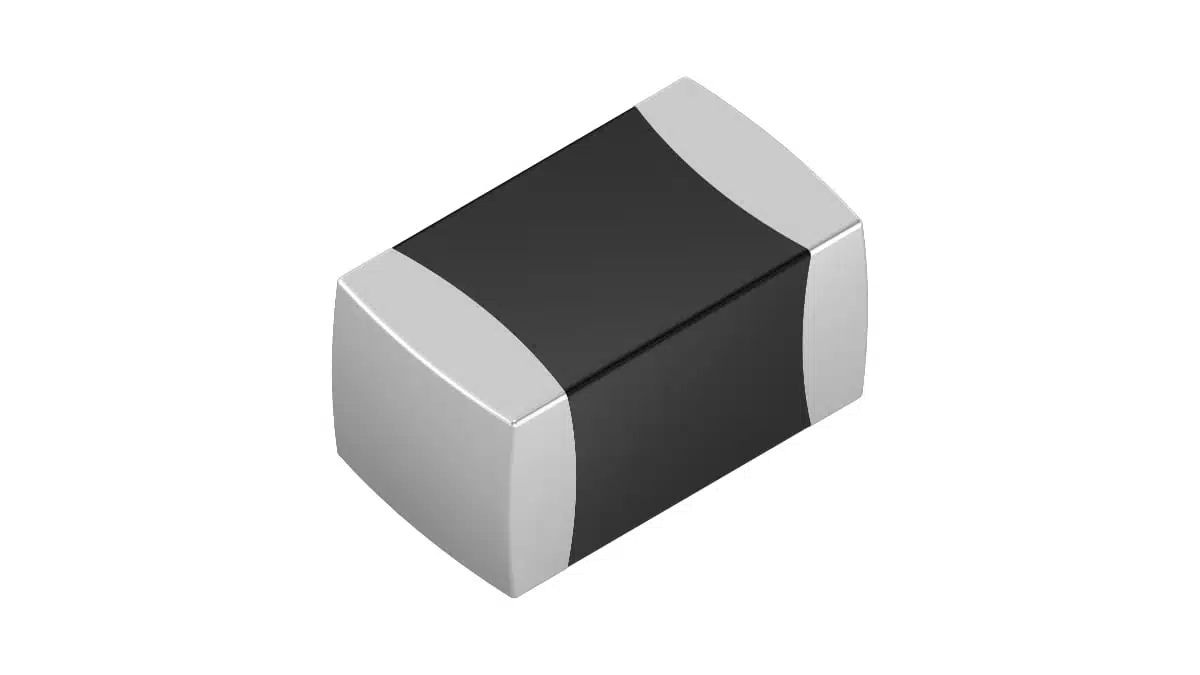
TDK has introduced the standard X series of surface-mount multilayer varistors for industrial transient-overvoltage protection.
The family covers power supplies, factory automation, industrial IoT and sensor interfaces, with case sizes spanning EIA 0402 to 2220. Its ceramic formulation enables lower-temperature sintering and a component CO₂-footprint reduction of up to 30% compared with standard MLVs.
Key features and benefits
- ESD protection up to 15 kV air discharge under IEC 61000-4-2.
- Response time below 0.5 ns.
- Capacitance options down to 6 pF for data-line protection.
- Surface-mount packages spanning EIA 0402 to 2220.
- Operation up to +125 °C without temperature derating.
- Customer-specific electrical adjustments.
- Tape-and-reel packaging for automated assembly.
The X series extends the ceramic technology platform used by the automotive X1 family into standard industrial applications. The new ceramic composition reduces sintering energy, while the raw material contributes a smaller CO₂ footprint.
Technical highlights
Working voltage and clamping voltage serve different purposes
The varistors connect in parallel with the circuit being protected. Their resistance decreases as voltage rises, creating a shunt path for transient current.
Selection requires separating working voltage, varistor voltage and clamping voltage. Working voltage governs continuous operation. Varistor voltage characterises the onset of conduction at a defined measurement current. Clamping voltage gives the voltage across the device at a higher, defined pulse current.
Two standard X-series devices illustrate the electrical choices available:
| Parameter | CT1210K50G_X | CT2220K30G_X |
|---|---|---|
| Ordering code | B72530X0500K062 | B72540X0300K062 |
| EIA case size | 1210 | 2220 |
| Maximum AC operating voltage | 50 V RMS | 30 V RMS |
| Maximum DC operating voltage | 65 V | 38 V |
| Varistor-voltage tolerance | ±10% | ±10% |
| Varistor voltage at 1 mA, +25 °C | 73.8–90.2 V | 42.3–51.7 V |
| Maximum clamping voltage | 135 V at 2.5 A | 77 V at 10 A |
| Maximum surge current, single 8/20 µs pulse | 200 A | 1,200 A |
| Maximum average power dissipation | 10 mW | 30 mW |
| Typical capacitance | 1,000 pF | 8,000 pF |
| Response time | <0.5 ns | <0.5 ns |
| Operating temperature | −55 to +125 °C | −55 to +125 °C |
Capacitance values in the table are measured at 1 kHz, 1 V and +25 °C. The CT1210K50G_X also has a maximum energy-absorption rating of 1,600 mJ for a 2 ms pulse.
The clamping values must be read together with their test currents. A 135 V clamping limit at 2.5 A is not a constant-voltage clamp across every transient condition. Likewise, the single-pulse surge-current rating is distinct from the maximum average power dissipation relevant to repeated events.
Package dimensions and assembly
Both example devices use Ag/Ni/Sn three-layer terminations.
| Mechanical parameter | CT1210K50G_X | CT2220K30G_X |
|---|---|---|
| Length | 3.2 ±0.3 mm | 5.7 ±0.4 mm |
| Width | 2.5 ±0.2 mm | 5.0 ±0.4 mm |
| Maximum height | 1.7 mm | 2.5 mm |
| Packing quantity | 2,000 pieces/reel | 1,000 pieces/reel |
The assembly profiles support three reflow cycles. Soldering-iron repair should be avoided; hot-air repair methods are recommended. Adequate preheating and controlled cooling matter because thermal shock can crack the ceramic.
Typical applications
Target applications include transient-overvoltage protection in:
- Power supplies.
- Factory-automation equipment.
- Industrial IoT devices.
- Sensor interfaces.
Power-supply and automation circuits require the continuous voltage rating and transient-current capability to be considered together. The CT2220K30G_X combines a 38 V DC operating limit with a single-pulse surge-current rating of 1,200 A for an 8/20 µs waveform. The CT1210K50G_X accommodates continuous voltages up to 65 V DC, with a 200 A single-pulse rating in a 1210 package.
These are shunt-protection devices, not series current-carrying components. The surge-current rating therefore concerns the current diverted during a transient, rather than the normal load current of the protected circuit.
Application fit
Signal interfaces versus power-line protection
Capacitance is a central selection parameter for sensor and data interfaces. The family includes options down to 6 pF, while the two devices above have typical capacitances of 1,000 pF and 8,000 pF. Selecting a device for its surge rating does not establish its suitability for a signal line.
The voltage class, clamping behaviour and capacitance must fit the same circuit position. The family’s minimum capacitance is not a characteristic shared by every member.
Transient protection versus sustained overvoltage
The X-series varistors provide transient suppression rather than continuous voltage regulation. They are not suitable for voltage-stabilisation duties requiring sustained power dissipation.
Repeated pulses also introduce a thermal constraint. If the device has insufficient cooling time between events, average dissipation becomes a selection limit alongside peak current. This makes pulse repetition and cooling conditions part of the protection design, rather than treating the maximum surge-current figure as a complete rating.
Design-in notes for engineers
- Match the maximum AC or DC operating voltage to the highest continuous voltage at the protected node.
- Evaluate clamping voltage at the relevant transient current against the protected circuit’s voltage withstand.
- Assess pulse waveform, peak current and repetition together with energy absorption and average dissipation.
- Connect the varistor in parallel with the protected circuit and minimise inductance in the transient-current path.
- Use the device-specific land pattern and assembly profile when preparing the PCB footprint and manufacturing process.
- Prevent condensation and exposure to liquids, corrosive gases or saline spray; the components are primarily intended for enclosed equipment.
- Validate the final selection under actual operating and worst-case transient conditions before production release.
Further reading
- EMC Design Fundamentals: Safe Use of Varistors and Common Mode Chokes in Mains and Data-Line Filters
- TDK Unveils New Family of eco-friendly SMD Varistors
Source
This article is based on the TDK product announcement and official product documentation. Engineers should refer to the current manufacturer datasheet for final design and qualification.
References
- TDK extends eco-friendly SMD varistors with X series for standard applications, TDK Electronics, October 14, 2026.
- Multilayer Varistors, TDK Electronics.[tdk-electronics.tdk]
- CTVS — Multilayer varistors, standard series: CT1210K50G_X, TDK Electronics, March 12, 2026.
- CTVS — Multilayer varistors, standard series: CT2220K30G_X, TDK Electronics, February 19, 2026.