



Passive Components Blog
No Result
View All Result
  • Home
  • NewsFilter
    • All
    • Aerospace & Defence
    • Antenna
    • Applications
    • Automotive
    • Capacitors
    • Circuit Protection Devices
    • electro-mechanical news
    • Filters
    • Fuses
    • Inductors
    • Industrial
    • Integrated Passives
    • inter-connect news
    • Market & Supply Chain
    • Market Insights
    • Medical
    • Modelling and Simulation
    • New Materials & Supply
    • New Technologies
    • Non-linear Passives
    • Oscillators
    • Passive Sensors News
    • Resistors
    • RF & Microwave
    • Telecommunication
    • Weekly Digest

    Vishay Releases High‑Current Radial Inductors up to 209 A

    May 2026 Interconnect, Passives and Electromechanical Components Market Insights

    Passive Components Enable Safe and Reliable ADAS Architectures

    Current Sense Transformer Datasheet and Design‑in Guide

    Designing a USB Type‑C Flyback Planar Transformer with Frenetic’s Planar Tool

    YMIN Releases Square Supercapacitors for AI Server Power System

    Exxelia Extends Temperature Range of its PP Film Capacitors to 140C

    How Long-Term Storage Causes Aging in Electronic Components

    Nichicon Presents Self-Charging LTO Board for Maintenance-Free IoT Nodes

    Trending Tags

    • Ripple Current
    • RF
    • Leakage Current
    • Tantalum vs Ceramic
    • Snubber
    • Low ESR
    • Feedthrough
    • Derating
    • Dielectric Constant
    • New Products
    • Market Reports
  • VideoFilter
    • All
    • Antenna videos
    • Capacitor videos
    • Circuit Protection Video
    • Filter videos
    • Fuse videos
    • Inductor videos
    • Inter-Connect Video
    • Non-linear passives videos
    • Oscillator videos
    • Passive sensors videos
    • Resistor videos

    Current Sense Transformer Datasheet and Design‑in Guide

    Designing a USB Type‑C Flyback Planar Transformer with Frenetic’s Planar Tool

    Magnetics Design in High‑Frequency GaN Converters

    Qi2 Wireless Charging: Inductors, Capacitors and EMC Filters

    Two‑capacitor paradox explained for engineers

    Capacitances of Nonlinear MLCCs: What Datasheets Don’t Tell You

    Tapped Inductor Buck Converter Fundamentals

    Planar vs Conventional Transformer: When it Make Sense

    Modeling Fringing Field Losses in Inductors & Transformers

    Trending Tags

    • Capacitors explained
    • Inductors explained
    • Resistors explained
    • Filters explained
    • Application Video Guidelines
    • EMC
    • New Products
    • Ripple Current
    • Simulation
    • Tantalum vs Ceramic
  • Knowledge Blog
  • DossiersNew
  • Suppliers
    • Who is Who
  • PCNS
    • PCNS 2025
    • PCNS 2023
    • PCNS 2021
    • PCNS 2019
    • PCNS 2017
  • Events
  • Home
  • NewsFilter
    • All
    • Aerospace & Defence
    • Antenna
    • Applications
    • Automotive
    • Capacitors
    • Circuit Protection Devices
    • electro-mechanical news
    • Filters
    • Fuses
    • Inductors
    • Industrial
    • Integrated Passives
    • inter-connect news
    • Market & Supply Chain
    • Market Insights
    • Medical
    • Modelling and Simulation
    • New Materials & Supply
    • New Technologies
    • Non-linear Passives
    • Oscillators
    • Passive Sensors News
    • Resistors
    • RF & Microwave
    • Telecommunication
    • Weekly Digest

    Vishay Releases High‑Current Radial Inductors up to 209 A

    May 2026 Interconnect, Passives and Electromechanical Components Market Insights

    Passive Components Enable Safe and Reliable ADAS Architectures

    Current Sense Transformer Datasheet and Design‑in Guide

    Designing a USB Type‑C Flyback Planar Transformer with Frenetic’s Planar Tool

    YMIN Releases Square Supercapacitors for AI Server Power System

    Exxelia Extends Temperature Range of its PP Film Capacitors to 140C

    How Long-Term Storage Causes Aging in Electronic Components

    Nichicon Presents Self-Charging LTO Board for Maintenance-Free IoT Nodes

    Trending Tags

    • Ripple Current
    • RF
    • Leakage Current
    • Tantalum vs Ceramic
    • Snubber
    • Low ESR
    • Feedthrough
    • Derating
    • Dielectric Constant
    • New Products
    • Market Reports
  • VideoFilter
    • All
    • Antenna videos
    • Capacitor videos
    • Circuit Protection Video
    • Filter videos
    • Fuse videos
    • Inductor videos
    • Inter-Connect Video
    • Non-linear passives videos
    • Oscillator videos
    • Passive sensors videos
    • Resistor videos

    Current Sense Transformer Datasheet and Design‑in Guide

    Designing a USB Type‑C Flyback Planar Transformer with Frenetic’s Planar Tool

    Magnetics Design in High‑Frequency GaN Converters

    Qi2 Wireless Charging: Inductors, Capacitors and EMC Filters

    Two‑capacitor paradox explained for engineers

    Capacitances of Nonlinear MLCCs: What Datasheets Don’t Tell You

    Tapped Inductor Buck Converter Fundamentals

    Planar vs Conventional Transformer: When it Make Sense

    Modeling Fringing Field Losses in Inductors & Transformers

    Trending Tags

    • Capacitors explained
    • Inductors explained
    • Resistors explained
    • Filters explained
    • Application Video Guidelines
    • EMC
    • New Products
    • Ripple Current
    • Simulation
    • Tantalum vs Ceramic
  • Knowledge Blog
  • DossiersNew
  • Suppliers
    • Who is Who
  • PCNS
    • PCNS 2025
    • PCNS 2023
    • PCNS 2021
    • PCNS 2019
    • PCNS 2017
  • Events
No Result
View All Result
Passive Components Blog
No Result
View All Result

Vishay Releases New Generation of Automotive EMI Shielded Inductor

5.6.2024
Reading Time: 3 mins read
A A

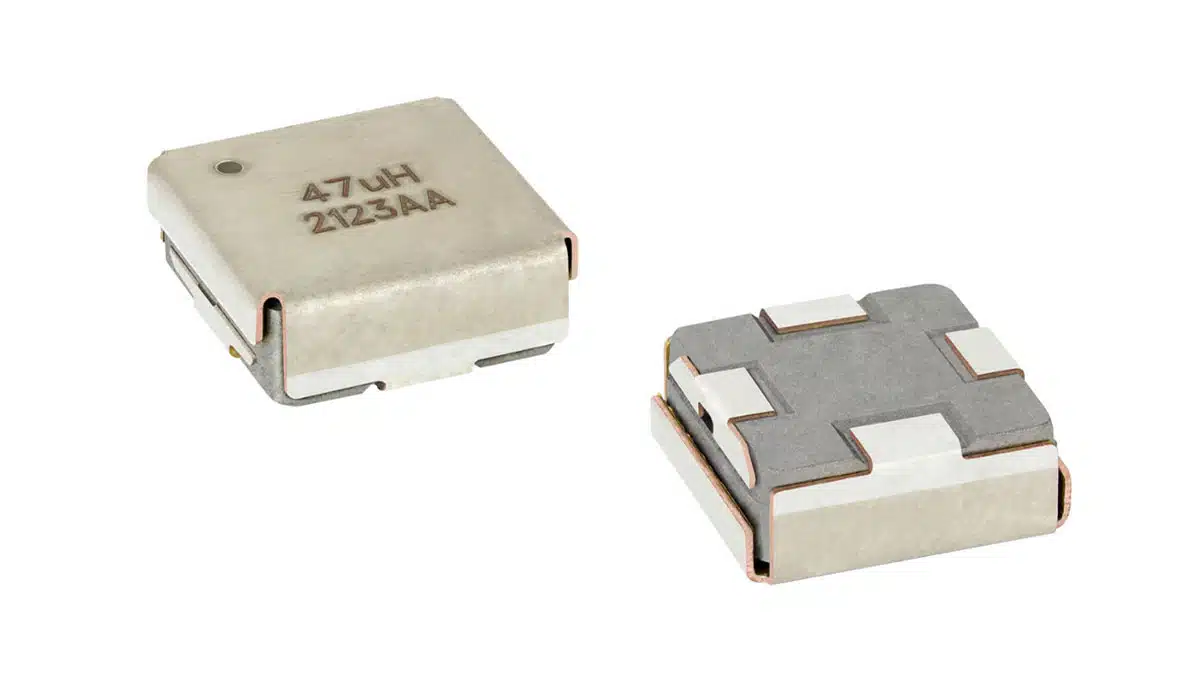
Vishay Intertechnology releases second-generation automotive grade IHLE® inductor with integrated EMI shield in 4040 case size.

Vishay Intertechnology, Inc. (NYSE: VSH) expanded its IHLE® series of low profile, high current power inductors featuring integrated E-field shields with a new second-generation Automotive Grade device in the 10 mm by 10 mm 4040 case size.

RelatedPosts

Vishay Releases High‑Current Radial Inductors up to 209 A

SPICE Simulation of Non-Linear Resistors: Vishay’s Thermistor and PPTC Modelling Ecosystem

Vishay Extends Power Inductors for DC/DC with 1212 Compact Case

Offering an improved shield design over previous-generation solutions, and polarity marked for more consistent EMI performance, the Vishay Dale IHLE-4040DDEW-5A lowers costs and saves board space by potentially eliminating the need for separate board-level Faraday shielding.

Compared to traditional composite inductors, the device released today contains the electric and magnetic fields associated with EMI in a tin-plated copper integrated shield. When the shield is connected to ground, the IHLE-4040DDEW-5A provides up to 20 dB reduction in radiated noise interference, and a further 6 dB reduction in magnetic flux leakage to minimize crosstalk to nearby board components. The inductor features continuous high temperature operation to +155 °C and improved operating and isolation voltage ratings of 75 V and 100 V, respectively.

The IHLE-4040DDEW-5A power inductor is optimized for energy storage in switch mode power supplies and provides excellent noise attenuation when used as a DC power line choke. AEC-Q200 qualified, the device is designed for filtering and DC/DC conversion in entertainment / navigation systems; LED drivers; and noise suppression for motors, automotive domain control units (DCU), and other noise-sensitive applications.

Packaged in a 100 % lead (Pb)-free, magnetically shielded, iron alloy encapsulant, the IHLE-4040DDEW-5A offers high resistance to thermal shock, moisture, and mechanical shock from the additional mounting support provided by its two shield terminals. The inductor is RoHS-compliant, halogen-free, and Vishay Green.

Samples and production quantities of the IHLE-4040DDEW-5A are available now, with lead times of 16 weeks.

 Low EndHigh End
Inductance @ 100 kHz (μH)0.4768
DCR typ. @ 25 °C (mΩ)1.55240
DCR max. @ 25 °C (mΩ)1.66252
Heat rating current typ. (A)(1)322.6
Saturation current typ. (A)(2)283.5
Saturation current typ. (A)(3)40.14.9
SRF typ. (MHz)32.03.5
Case size40404040
Part numberIHLE4040DDEWR47M5AIHLE4040DDEW680M5A
Device Specification
  • (¹) DC current (A) that will cause an approximate ΔT of 40 °C
  • (²) DC current (A) that will cause L0 to drop approximately 20 %
  • (3) DC current (A) that will cause L0 to drop approximately 30 %
Related

Source: Vishay

Recent Posts

Vishay Releases High‑Current Radial Inductors up to 209 A

29.5.2026
8

May 2026 Interconnect, Passives and Electromechanical Components Market Insights

29.5.2026
38

Passive Components Enable Safe and Reliable ADAS Architectures

28.5.2026
41

Current Sense Transformer Datasheet and Design‑in Guide

27.5.2026
41

Designing a USB Type‑C Flyback Planar Transformer with Frenetic’s Planar Tool

27.5.2026
26

YMIN Releases Square Supercapacitors for AI Server Power System

27.5.2026
40

Exxelia Extends Temperature Range of its PP Film Capacitors to 140C

27.5.2026
29

How Long-Term Storage Causes Aging in Electronic Components

26.5.2026
74

Nichicon Presents Self-Charging LTO Board for Maintenance-Free IoT Nodes

26.5.2026
20

Upcoming Events

Jun 2
16:00 - 17:00 CEST

Calculation, Simulation and Measurement of 800V EMC Filters

Jun 16
16:00 - 17:00 CEST

EMC with EMC – EMC‑compliant design with electromechanical connectors

View Calendar

Popular Posts

  • Buck Converter Design and Calculation

    0 shares
    Share 0 Tweet 0
  • Boost Converter Design and Calculation

    0 shares
    Share 0 Tweet 0
  • Flyback Converter Design and Calculation

    0 shares
    Share 0 Tweet 0
  • MLCC and Ceramic Capacitors

    0 shares
    Share 0 Tweet 0
  • LLC Resonant Converter Design and Calculation

    0 shares
    Share 0 Tweet 0
  • Capacitor Charging and Discharging

    0 shares
    Share 0 Tweet 0
  • What Electronics Engineer Needs to Know About Passive Low Pass Filters

    0 shares
    Share 0 Tweet 0
  • Dual Active Bridge (DAB) Topology

    0 shares
    Share 0 Tweet 0
  • Ripple Current and its Effects on the Performance of Capacitors

    3 shares
    Share 3 Tweet 0
  • SEPIC Converter Design and Calculation

    0 shares
    Share 0 Tweet 0

Newsletter Subscription


Passive Components Blog

© EPCI - Leading Passive Components Educational and Information Site

  • Home
  • Privacy Policy
  • EPCI Membership & Advertisement
  • About

No Result
View All Result
  • Home
  • Knowledge Blog
  • Dossiers
  • PCNS

© EPCI - Leading Passive Components Educational and Information Site

This website uses cookies. By continuing to use this website you are giving consent to cookies being used. Visit our Privacy and Cookie Policy.
Go to mobile version