
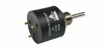













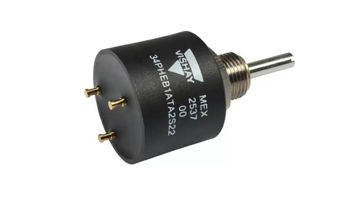
Vishay’s new 34 PHE multi-turn absolute position sensor is a ready-to-use Hall-effect module aimed at demanding motion control and displacement tracking applications.
The new Vishay position sensor combines multi-turn absolute angle measurement, high linearity, and long service life in a compact 7/8 inch body, with a cost point significantly below previous-generation solutions.
Key features and benefits
- Multi-turn absolute position sensing with a total electrical angle of 3600° over 10 turns, allowing precise tracking of linear or rotary displacement without mechanical gearing or external counters.
- Non-contacting Hall-effect technology, reducing wear and friction compared to potentiometer-based solutions and supporting a lifespan above 10 million cycles in dynamic applications.
- High accuracy and resolution, with linearity down to ±1% over the full stroke and a 1° resolution, suitable for servo loop motion control and closed-loop actuators.
- Compact form factor, integrating the full sensing and signal-conditioning electronics into a 7/8 in (22.2 mm) diameter body for tight space constraints in industrial machines and vehicles.
- Cost-optimized design, offered at roughly 40% lower cost than previous-generation devices in the same class, making multi-turn absolute sensing accessible for mid-range and cost-sensitive platforms.
- Harsh-environment robustness, including IP65-rated sealing, vibration endurance up to 20 g, and shock resistance up to 50 g, enabling reliable operation in mobile machinery and outdoor equipment.
- Built-in protection circuitry, with integrated reverse-voltage and overvoltage input protection at -14 VDC and +28 VDC, reducing the need for external protection components on the wiring harness.
- Flexible output configuration, selectable as single or dual analog ratiometric outputs or digital PWM output, allowing direct interface to typical industrial and automotive control electronics.
- Dual redundant sensing capability, where oppositely tracking dual outputs provide inherent fault detection support for higher functional safety levels without complex external logic.
- True power-on behavior, reporting the absolute position immediately at power up without re-homing or calibration routines, which simplifies system start-up and eliminates battery-backed encoders.
- Standard 5 V supply, operating from 5 VDC ±10% with a typical supply current below 8.5 mA (single output), compatible with common microcontroller and ECU supply rails.
Typical applications
The 34 PHE is intended for motion and position sensing in industrial and mobile equipment where environmental stress and long-term stability are key requirements.
- Industrial motor and actuator displacement tracking in servo systems and position-controlled drives.
- Linear actuators for solar panel tracking, where multi-turn stroke and outdoor exposure demand sealed and stable sensing.
- Flow control valve positioning in process control, HVAC, or hydraulic systems.
- Throttle and pedal position sensors in agricultural machinery and off-highway vehicles needing long-life, absolute feedback over multiple turns.
- Position sensing in railway equipment and shipboard systems, where vibration, shock, and contamination levels exceed typical industrial conditions.
A typical use case is to mount the sensor directly to an actuator shaft or lead screw, using the multi-turn capability to follow several revolutions of travel while still reporting a unique absolute position after every power cycle.
Technical highlights
Measurement and performance
- Measurement type: multi-turn absolute position for rotary or equivalent linear displacement.
- Total electrical angle: 3600° distributed across 10 turns, enabling multi-revolution coverage.
- Resolution: 1° per step, suitable for medium-precision motion control and position monitoring.
- Linearity: down to ±1% of full stroke, reducing systematic error and easing calibration effort in the application.
- Lifespan: greater than 10 million cycles, thanks to non-contact Hall-effect sensing and robust mechanical construction.
In practice, the ±1% linearity means that the sensor’s output will closely track the ideal position-versus-output curve over the entire travel, limiting the need for complex correction tables in the controller.
Mechanical and environmental characteristics
- Body diameter: 7/8 in (22.2 mm), supporting integration into compact housings and retrofits where space is limited.
- Environmental sealing: IP65 rating, providing protection against dust ingress and low-pressure water jets, typical in industrial and mobile environments.
- Vibration resistance: tested up to 20 g at high frequency, suitable for engines, pumps, and mobile machinery.
- Shock resistance: withstands mechanical shocks up to 50 g, helping maintain calibration under mechanical impacts and transport handling.
- Mounting aid: integrated locating peg on the mounting face to simplify alignment, prevent housing rotation, and improve long-term stability of the mechanical reference.
The locating peg is particularly useful for design engineers: it can be used as a mechanical key in the housing or bracket, avoiding small misalignments that would otherwise degrade accuracy or require tedious mechanical adjustment.
Electrical characteristics and outputs
- Supply voltage: 5 VDC ±10%, matching standard logic and sensor supply rails in industrial controllers and automotive ECUs.
- Supply current: < 8.5 mA typical for single-output configuration, aiding low-power designs and simplifying sensor channel current budgeting.
- Recommended load resistance: 1 kΩ for both analog and PWM outputs, providing a straightforward design guideline for input stages.
- Output modes:
- Single analog ratiometric output for simple position feedback into ADC inputs.
- Dual analog ratiometric outputs for redundant, oppositely tracking signals in safety applications.
- Digital PWM output for controllers preferring duty-cycle-based position encoding immune to some analog noise sources.
- Protection features: integrated reverse-voltage protection down to -14 VDC and overvoltage protection up to +28 VDC on the input, helping the device survive wiring errors or transient events.
From a wiring standpoint, the integrated protection simplifies harness design; design engineers can often avoid additional discrete TVS diodes or polarity protection on the sensor side, concentrating protective elements closer to the controller.
Functional behavior
- True power-on absolute device: the sensor reports the correct multi-turn position immediately at power-up, without any homing sequence or initialization routine.
- No backup power required: absolute multi-turn behavior is maintained without battery backup, which helps reduce maintenance, avoids battery failure modes, and simplifies environmental compliance.
- Customization options: the sensor can be tailored to meet more demanding requirements according to the manufacturer’s datasheet and custom capabilities, such as specific signal ranges or mechanical adaptations.
In applications where a power loss might occur frequently (e.g., mobile machinery or intermittent systems), this true power-on behavior eliminates the need for limit switches or reference marks to re-establish position, saving both hardware and commissioning time.
Ordering and logistics
- Product series: 34 PHE multi-turn absolute position sensor.
- Status: released for samples and production quantities.
- Lead time: 14 weeks for standard deliveries as indicated at launch.
- Sample access: available through the manufacturer’s sample request portal and standard distribution channels, subject to regional availability.
| Item | Description |
|---|---|
| Series | 34 PHE multi-turn position sensor |
| Technology | Non-contact Hall-effect |
| Total electrical angle | 3600° over 10 turns |
| Body diameter | 7/8 in (22.2 mm) |
For exact ordering codes, shaft and interface variants, and any optional mechanical customizations, engineers and purchasers should refer directly to the official product page and datasheet as provided by the manufacturer.
Design-in notes for engineers
- Check mechanical coupling and alignment
Ensure that the actuator or shaft coupling to the sensor can transmit motion accurately across the full 10-turn range without backlash or slip. The locating peg should be used to prevent housing rotation, and any mechanical adapter should be designed to avoid off-axis loading that could degrade long-term stability. - Account for environmental exposure
With IP65 sealing, the sensor is suitable for dusty and splash-prone environments, but continuous submersion or high-pressure wash-down may require additional protective housings. System designers should verify actual environmental conditions and consider sealing gaskets or covers when the sensor is mounted externally. - Plan electrical protection and wiring
Although reverse-voltage and overvoltage protections are integrated, wiring practices should still follow standard EMC and safety guidelines. Use twisted pairs or shielded cables as appropriate, and confirm that controller input circuits provide the recommended load resistance of around 1 kΩ for analog or PWM operation. - Select the right output interface for the controller
For simple control loops, a single analog ratiometric output can directly feed an ADC channel; in safety-related systems, dual oppositely tracking analog outputs enable cross-checking and fault detection. PWM output can be preferred in noisy environments or longer cable runs, as the controller can decode duty cycle with good immunity to certain analog disturbances. - Consider functional safety requirements early
Where the sensor is part of a safety function (e.g., limiting valve travel or controlling throttle position), use dual outputs and design diagnostics to detect discrepancies between the two signals. The internal redundancy of the sensor should be combined with system-level diagnostics, such as plausibility checks and range monitoring, to achieve the desired safety integrity level. - Evaluate calibration and error budgets
While the sensor offers ±1% linearity, overall system accuracy also depends on mechanical tolerances, mounting offsets, and controller-side scaling. During design-in, consider a calibration procedure in the control software to map raw sensor values to physical position, particularly for applications with tight tolerance requirements. - Verify power-on behavior in system tests
The true power-on absolute function is a key advantage; designers should test power cycling and brownout scenarios to confirm that the system reacts correctly to immediate absolute position reporting, especially in servo loops where sudden motion could occur if position is misinterpreted. - Consult the datasheet for special conditions
For operating temperatures, detailed EMC test conditions, and any specific derating information, refer directly to the official datasheet. Use “according to manufacturer datasheet” as the baseline for detailed numeric limits during documentation, avoiding assumptions on ranges beyond what is explicitly specified.
Source
This article is based on information provided in the official Vishay Intertechnology press release and associated product documentation for the 34 PHE multi-turn absolute position sensor, complemented with neutral technical context relevant to motion control and position sensing applications.