


Vishay Intertechnology has introduced six new SMD polymer PTC series that target USB‑C, PoE, battery‑powered devices, and industrial automation where fast trip behavior and low series resistance are increasingly important for efficiency and reliability.
Surface‑mount polymer PTC thermistors are a compact, resettable way to protect low‑voltage circuits against overcurrent events without fuses or service interventions. These Vishay BCcomponents devices cover case sizes from 0603 to 2920 with holding currents up to 5 A and trip currents up to 10 A, giving design engineers a broad selection range for fine‑tuning protection thresholds while minimizing PCB area and power loss.
Key features and benefits
- Resettable overcurrent protection for low‑voltage DC circuits, avoiding the need for discrete fuses and manual replacement after a fault.
- High holding current up to 5.0 A, allowing use in high‑current USB‑C ports, PoE links, and battery tools without nuisance tripping under normal load.
- Fast trip times down to 50 ms, providing rapid response to short‑circuit or overload conditions and reducing stress on upstream power stages.
- Low resistance down to 5 mΩ, minimizing voltage drop and power loss so protected rails maintain regulation and overall system efficiency.
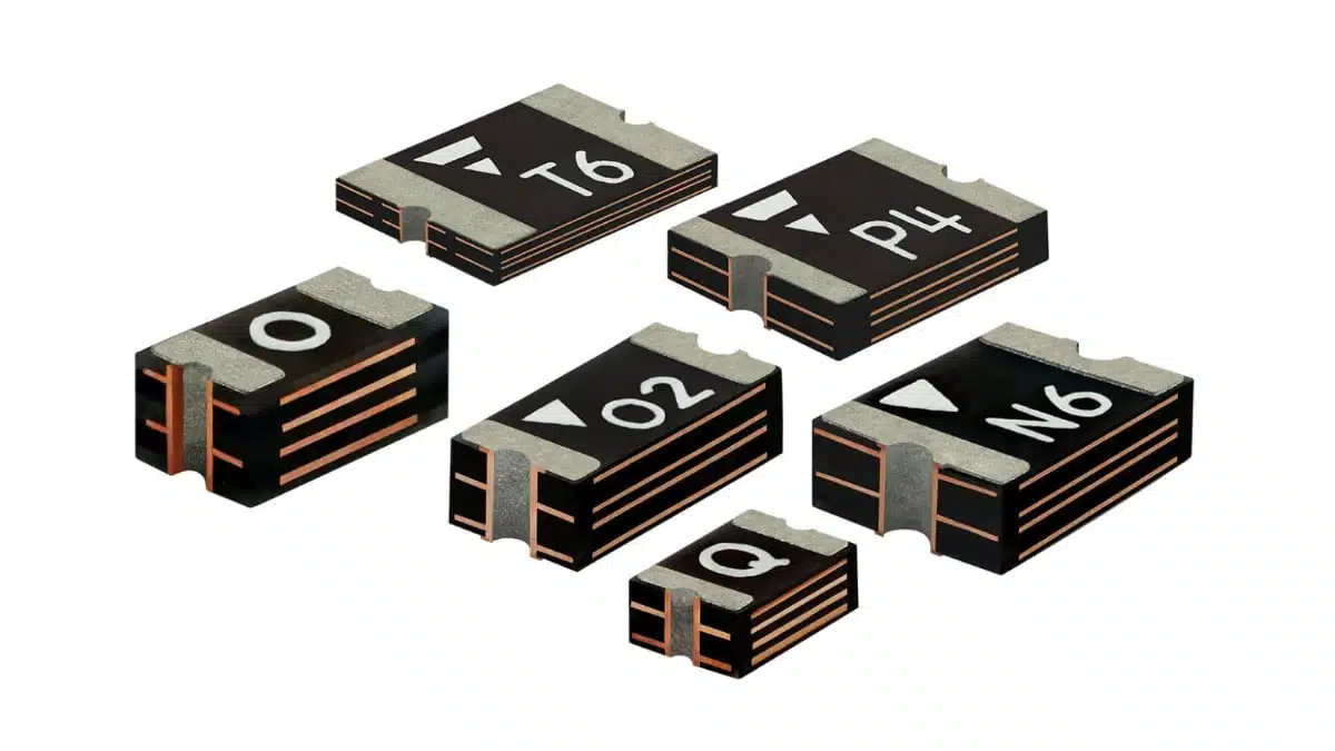
- Six SMD case sizes (0603, 0805, 1206, 1210, 1812, 2920), giving layout flexibility from space‑constrained handheld boards to higher‑power industrial PCBs.
- Low component height from 0.3 mm to 2 mm, supporting dense designs and assemblies where overall stack‑up height is critical.
- RoHS‑compliant and halogen‑free construction, aligning with current environmental and regulatory requirements across consumer and industrial markets.
- Compatibility with Pb‑free reflow up to 260 °C, simplifying assembly in standard SMT lines without special solder profiles.
- SPICE and 3D models available, enabling electrical behavior simulation and mechanical integration early in the design cycle.
Typical applications
Vishay’s PPTC0603E3, PPTC0805E3, PPTC1206E3, PPTC1210E3, PPTC1812E3, and PPTC2920E3 series are oriented toward low‑voltage DC rails where resettable current limiting and space efficiency are key.
Typical use cases include:
- USB‑C ports and hubs in notebooks, docking stations, and desktop computers, protecting against cable shorts and device faults.
- Power over Ethernet interfaces in IP cameras, VoIP phones, small switches, and other PoE‑powered peripherals.
- Battery‑powered industrial tools such as handheld testers, portable instrumentation, and cordless power tools.
- Consumer battery‑powered devices and appliances including smart home gear, small household appliances, and wearable chargers.
- Industrial automation modules (I/O cards, motor controllers, PLC extensions) where each output channel needs independent current limiting.
- Home automation heating and control systems, protecting low‑voltage actuator and sensor lines.
In many of these applications polymer PTCs are used on the supply line feeding a connector, module, or load branch, acting as a self‑resetting “electronic fuse” when sustained overcurrent raises their temperature above the switching threshold.
Technical highlights
The six series share common polymer PTC behavior but differ in case size and electrical ratings, giving a structured ladder of options for various power levels.
Series overview
| Series | Case size | Ihold range (A) | Itrip range (A) | Vmax range (VDC) | Imax range (A) |
|---|---|---|---|---|---|
| PPTC0603E3 | 0603 | 0.02 – 0.5 | 0.06 – 1.0 | 6 – 60 | 40 |
| PPTC0805E3 | 0805 | 0.05 – 0.75 | 0.15 – 1.5 | 6 – 30 | 40 – 100 |
| PPTC1206E3 | 1206 | 0.05 – 1.1 | 0.15 – 2.2 | 8 – 60 | 10 – 100 |
| PPTC1210E3 | 1210 | 0.05 – 1.5 | 0.15 – 3.0 | 6 – 90 | 10 – 100 |
| PPTC1812E3 | 1812 | 0.14 – 2.6 | 0.34 – 5.0 | 8 – 60 | 10 – 100 |
| PPTC2920E3 | 2920 | 0.5 – 5.0 | 1.0 – 10 | 15 – 60 | 10 – 40 |
Key electrical characteristics:
- Holding current (Ihold) up to 5.0 A determines the maximum continuous current the device can carry at a specified ambient without tripping, which is central to sizing the part for the normal operating load.
- Trip current (Itrip) up to 10 A specifies the approximate current at which the PTC will transition into a high‑resistance state for a given test condition, indicating the protection threshold for fault events.
- Maximum operating voltage (Vmax) ranges from 6 VDC to 90 VDC depending on series, covering typical 5 V, 12 V, 24 V, and 48 V rails and selected higher‑voltage industrial lines.
- Maximum fault current (Imax) up to 100 A indicates the highest short‑circuit current the device can safely withstand for the specified time without damage.
- Typical power dissipation (PD) spans roughly 0.5 W to 2 W, an important parameter for thermal design and derating under sustained operation near Ihold.
- Initial resistance (Rmin) and post‑trip resistance (R1 max) range from a few milliohms to several ohms, impacting both normal‑mode voltage drop and the level of impedance in the tripped state.
For example, PPTC2920E3 devices offer the highest Ihold and Itrip range for higher‑current rails, with Rmin down to 5 mΩ for minimal loss in normal operation and R1 max as low as 25 mΩ in some variants for relatively low residual resistance compared to smaller packages. In contrast, PPTC0603E3 focuses on low‑current, very space‑constrained designs where currents are modest but PCB area and height are critical.
Resistance behavior and efficiency
In polymer PTC thermistors the resistance increases sharply when the component’s internal temperature crosses a threshold during overcurrent, effectively limiting current by raising the circuit impedance. Under normal load the low Rmin values listed for these Vishay series help minimize both DC voltage drop and I²R losses, which is particularly important in:
- Long USB‑C traces where additional series resistance can impact power delivery compliance.
- PoE links where power budget per port is tightly managed.
- Battery‑powered devices where every milliwatt of loss reduces runtime.
At design time, engineers typically treat the PTC as a small series resistance in normal mode, then as a large dynamic resistance element under fault conditions. SPICE models from Vishay can help capture this behavior more accurately in system simulations.
Case size and height
The six case sizes (0603 through 2920) address different mechanical and power domains:
- 0603 and 0805: suited for densely packed consumer and portable boards where low profile and fine pitch are essential.
- 1206 and 1210: widely used in general‑purpose protection on 12 V to 24 V rails, balancing footprint and current.
- 1812 and 2920: used where higher fault currents and energy must be handled, for example in industrial or automotive‑like environments.
With heights from 0.3 mm to 2 mm, these SMD PTCs can fit under shielding cans or within constrained mechanical envelopes while still providing meaningful current limiting.
Design‑in notes for engineers
When designing with polymer PTC thermistors, the following points are useful for robust implementation:
- Define the current profile carefully. Evaluate steady‑state load, startup surges, and transient peaks so Ihold is comfortably above normal current but below sustained overload conditions.
- Consider ambient temperature. Polymer PTC trip behavior depends on temperature; higher ambient temperatures effectively lower the margin between normal operation and tripping, so derating is necessary.
- Check Vmax and Imax against worst‑case faults. Ensure the selected part can safely withstand the highest likely fault voltage and short‑circuit current without damage.
- Model voltage drop in normal operation. Use Rmin values and expected currents to calculate line drop, particularly on long traces or tight regulation rails.
- Place the device close to the load or connector. This helps protect the downstream wiring and simplifies understanding which branch is limited when multiple loads share a supply.
- Account for reset behavior. After a trip, the PTC will cool and gradually return towards its lower‑resistance state; design your system to manage auto‑retry or manual restart appropriately.
- Include layout provisions for thermal spreading. Packages with higher PD may benefit from wider copper areas to help remove heat under heavy load.
- Use available SPICE and 3D models early. Simulating the PTC’s effect on fault currents and mechanical integration can reduce iteration and avoid surprises in EMC and thermal testing.
For purchasing teams, key checks include series selection, voltage/current ratings, environmental compliance (RoHS, halogen‑free), and compatibility with existing SMT assembly flows, all of which are supported by these Vishay polymer PTC families.
Source
This article is based on information provided in the official Vishay Intertechnology press release about the PPTC0603E3, PPTC0805E3, PPTC1206E3, PPTC1210E3, PPTC1812E3, and PPTC2920E3 polymer PTC thermistor series and associated manufacturer documentation, with additional editorial context for design engineers and component buyers.


