


Vishay has expanded its ILHB series of Automotive Grade multilayer chip ferrite beads, adding higher current capability, smaller case sizes, and a broader impedance range for EMC noise reduction.
The Vishay ILHB chip ferrite beads updated portfolio targets high‑current filtering in space‑constrained automotive and industrial designs, with enhanced datasheet parameters that make ferrite bead selection more predictable for design engineers.
Key features and benefits
- Automotive Grade, AEC‑Q200 qualified ferrite beads designed for high‑reliability environments such as ECUs, power distribution, and energy management modules.
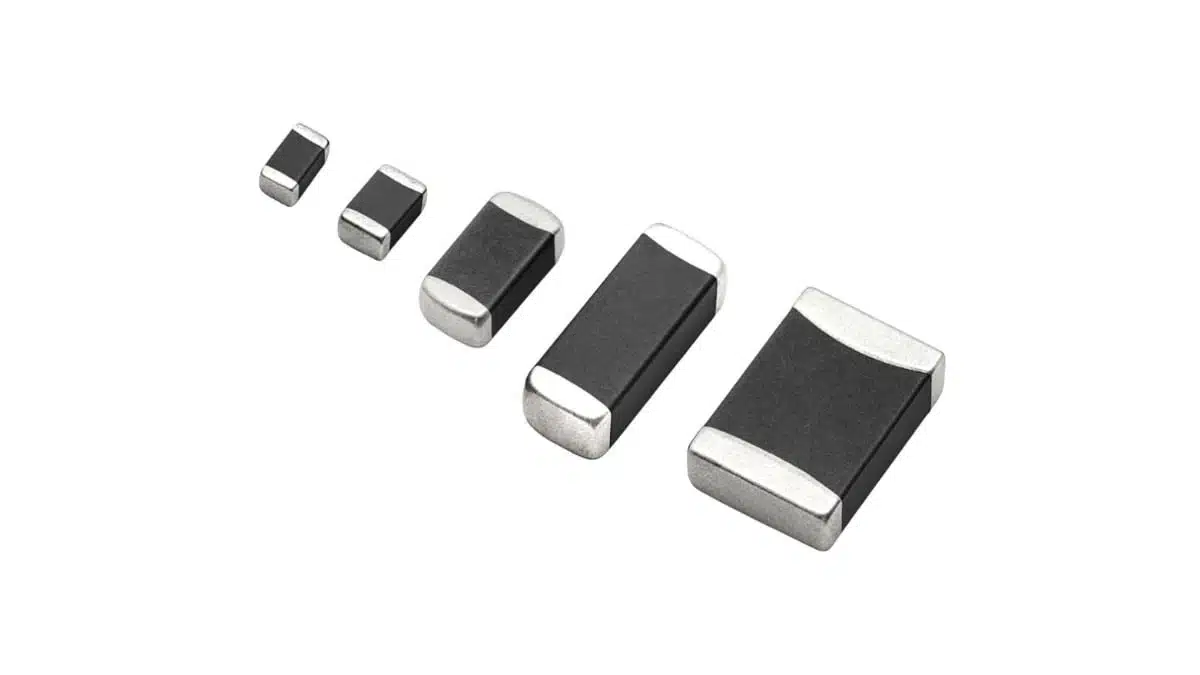
- Wide case size range from 0402 up to 1206, allowing designers to optimize between footprint, current rating, and impedance.
- Current handling up to 6 A, enabling high‑current power rail filtering without moving to larger through‑hole or wirewound components.
- Broad impedance range from 10 Ω to 2700 Ω at 100 MHz, supporting both low‑impedance “soft” filtering and high‑impedance aggressive EMI suppression on noisy lines.
- Improved current capability for a given size and impedance, with up to roughly two to three times the current rating compared to previous options in the same package class according to the manufacturer.
- Extended set of design parameters in the datasheet (impedance peak, peak frequency, nominal impedance drop‑off, XL/XR crossover) to support more accurate frequency‑domain behavior estimation.
- -55 °C to +125 °C operating temperature range, suitable for under‑hood and harsh industrial environments.
- RoHS‑compliant, halogen‑free, Vishay Green construction, aligning with current environmental and regulatory requirements.
Typical applications
The extended ILHB family targets high‑current, high‑frequency, and signal‑specific filtering tasks in a wide range of electronic systems where designers must meet EMC limits without sacrificing efficiency or board space.
- Automotive energy distribution and management systems (power distribution units, battery junction boxes, DC/DC converters).
- Automotive control units and infotainment electronics where supply rails and communication lines require EMI suppression.
- Industrial automation systems and motor drives, including I/O modules and distributed power rails.
- Home and building controls (smart thermostats, HVAC controllers, lighting controls) with switching regulators or communication buses.
- Computers and peripherals (motherboards, SSDs, graphics cards, printers) where high‑speed digital lines and power rails need noise attenuation.
- Consumer devices and white goods with compact SMPS stages.
- Medical instrumentation, avionics, and telecom infrastructure where robust EMC performance and Automotive Grade robustness are beneficial.
In many of these use cases, a compact multilayer chip ferrite bead provides a simple series impedance element that attenuates high‑frequency noise without significantly affecting DC or low‑frequency operation.
Technical highlights
The table below summarizes the core mechanical and electrical ranges for the ILHB series by case size. All values are according to the manufacturer’s device specification table and datasheets.
ILHB case sizes and key ranges
| Case size | Part family | Dimensions (mm) | Z at 100 MHz (Ω) | Max DCR (mΩ) | Rated DC I at 85 °C (A) |
|---|---|---|---|---|---|
| 0402 | ILHB‑0402 | 1.0 × 0.5 × 0.5 | 10 to 1800 | 18 to 2400 | 0.05 to 3.1 |
| 0603 | ILHB‑0603 | 1.6 × 0.8 × 0.8 | 22 to 2500 | 7 to 1800 | 0.05 to 6 |
| 0805 | ILHB‑0805 | 2.0 × 1.2 × 0.85 | 17 to 2700 | 10 to 800 | 0.2 to 6 |
| 1008 | ILHB‑1008 | 2.5 × 2.0 (thick per datasheet) | 300 to 600 | 30 | 4 |
| 1206 | ILHB‑1206 | 3.2 × 1.6 (thick per datasheet) | 19 to 1000 | 10 to 300 | 0.5 to 6 |
Some practical interpretations of these parameters for design engineers:
- Z at 100 MHz gives a first‑order indication of how effective the bead will be at attenuating noise around typical switching frequencies, harmonics, and RF interference bands. Higher impedance at 100 MHz generally means stronger attenuation in that region, but device selection should also consider the full impedance versus frequency curve.
- DCR max directly impacts DC losses and self‑heating. Lower DCR parts are preferred for high‑current power rails to minimize voltage drop and efficiency loss.
- Rated DC current at 85 °C is defined as the DC current that produces a 40 °C temperature rise at 20 °C ambient, which provides a realistic derating point for automotive and industrial environments.
Extended datasheet parameters
The ILHB datasheets include additional parameters specifically aimed at making frequency‑domain design easier without deep graph analysis:
- Impedance peak value (Zpk) – the maximum impedance reached by the ferrite bead over frequency, important for identifying the most effective attenuation band.
- Frequency at impedance peak (F at Zpk) – indicates where the bead provides maximum attenuation, helping match the bead to dominant noise frequencies.
- Frequency at ZDO – the frequency above 100 MHz where the impedance drops to the nominal impedance value, indicating how quickly the bead’s effectiveness falls off at higher frequencies.
- XL/XR crossover point – the frequency where inductive reactance and resistive components of impedance are equal; below this point the behavior is more inductive, above it more resistive. This helps anticipate whether the bead will behave more like an inductor or a resistor at a given noise frequency.
For EMC engineers, these parameters simplify bead comparison and selection during early filter design and allow faster sanity checks when tuning EMI filters around specific switching frequencies.
Construction and environmental ratings
- Internal conductor based on silver with copper, nickel, and tin plating for good solderability and robustness.
- Operating temperature range from -55 °C to +125 °C suitable for many automotive zones and industrial environments.
- RoHS‑compliant, halogen‑free, and defined as Vishay Green according to the manufacturer’s environmental statements.
Design‑in notes for engineers
- Start from the noise spectrum, not just the nominal impedance. Select ILHB part numbers based on the dominant noise frequencies in your system, matching the Zpk and F at Zpk as closely as practical to those frequencies.
- Check XL/XR crossover versus your switching frequency. If your key noise components are below the crossover point, the bead will behave more inductively, which can interact with surrounding capacitances. Above the crossover, the bead is more resistive and tends to provide broadband damping.
- Balance impedance and current rating. High‑impedance versions typically have higher DCR and lower current capability. For high‑current rails up to several amperes, choose parts that provide adequate attenuation while keeping DCR and temperature rise within limits.
- Consider derating at elevated ambient temperatures. The rated DC current is specified at a defined temperature rise and ambient condition. In under‑hood or sealed enclosures, apply additional margin or refer to the manufacturer’s derating curves.
- Use small case sizes for local filtering close to IC pins. ILHB‑0402 and ILHB‑0603 are well suited for decoupling individual IC supply pins, high‑speed interfaces, or densely packed modules where layout proximity is critical.
- Reserve larger case sizes where thermal headroom is needed. ILHB‑0805, ILHB‑1008, and ILHB‑1206 offer higher current ratings and a larger thermal mass, which can be beneficial on main rails, distribution nodes, or noisy sub‑assemblies.
- Verify layout for thermal and EMC performance. Place beads in series with power traces or signal lines, keep loop areas small, and combine with suitable bypass capacitors to form effective LC or RC‑like filters. Avoid long stubs and ensure solid ground references.
- Check AEC‑Q200 grade against your target application. While the ILHB series is Automotive Grade and AEC‑Q200 qualified, always confirm that the exact part number meets internal OEM or Tier‑1 requirements and documentation.
For final component selection and simulation, designers should rely on the detailed curves and parameter tables in the ILHB datasheets rather than only the summarized figures.
Source
This article is based on Vishay Intertechnology’s official press release and associated ILHB series product information and has been adapted and commented from an independent technical perspective.


