


This article, edited from original article by Mark Laps, MLCC specialist at YAGEO Group, reviews why the industry is converging on 800 V DC distribution and how dedicated high-voltage C0G capacitors can underpin robust, next-generation AI power delivery solutions.
AI servers and the drive toward higher voltage power architectures
Artificial intelligence workloads are fundamentally reshaping data center design, driving sustained growth in AI processing demand and overall power consumption. The widespread deployment of large-scale AI platforms has expanded AI usage from consumer applications into enterprise and industrial environments, including automotive, healthcare, and manufacturing, which significantly increases processing power requirements and places new demands on data center power delivery architectures.
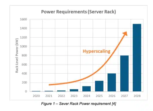
By 2028, global electricity consumption for data centers is projected to triple compared to the energy consumed in 2023. Modern AI systems are built around large groups of GPUs that work together at very high usage levels, behaving more like a single coordinated system than a collection of independent devices; high-speed connections allow these GPUs to operate in sync, enabling efficient scaling of workloads across many processors and resulting in step-function increases in both instantaneous and average rack-level power demand as well as high load transients.
Rack power densities that were once measured in tens of kilowatts are now advancing toward hundreds of kilowatts, with multi-megawatt AI racks under active development. These increases place substantial stress on conventional low-voltage power distribution architectures, which are constrained by current-handling capability, copper losses, physical cabling limitations, and overall efficiency, making traditional architectures increasingly unable to support AI-driven power growth.
Why the industry is moving toward 800 V
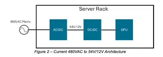
As AI platforms scale toward higher rack-level power densities, conventional low-voltage power distribution architectures are approaching their practical limits. Traditional in-rack distribution schemes based on 48 V or 54 V DC require very high currents, leading to increased I²R losses, larger copper conductors, and growing challenges in efficiency, thermal management, and physical integration.
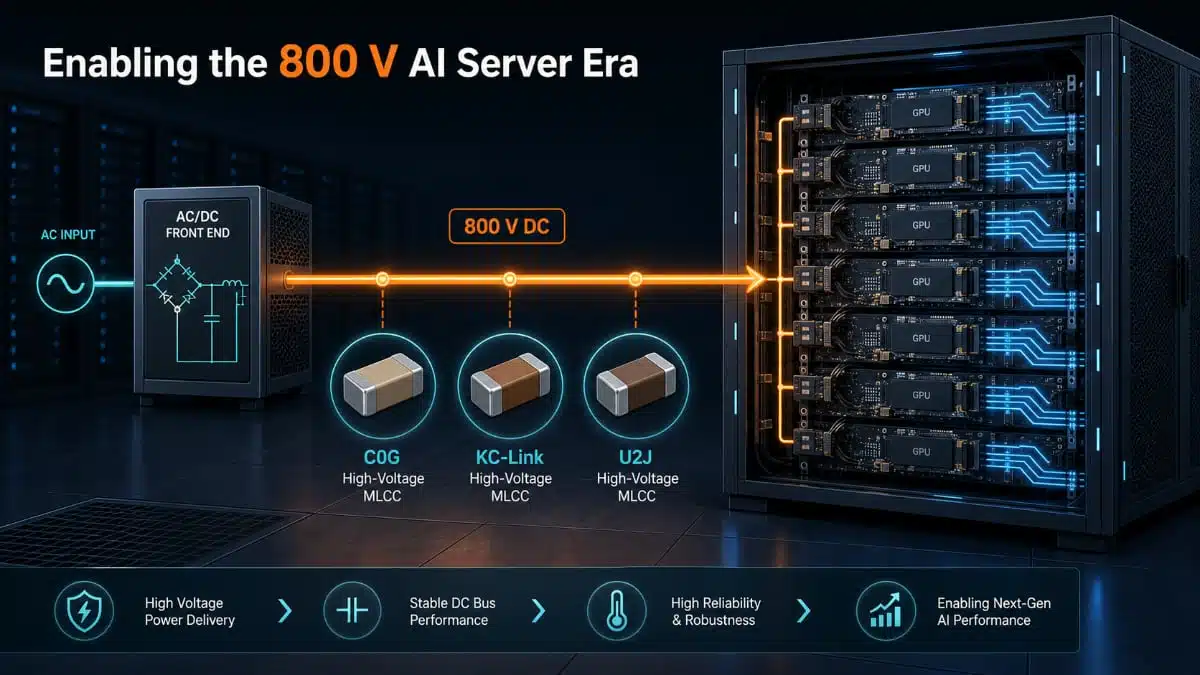
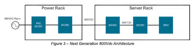
Raising the distribution voltage is a direct and effective means of addressing these limitations. Increasing the distribution level to around 800 V DC reduces current for a given power level, enabling significant reductions in copper size and resistive losses; compared to traditional 480 VAC to 54/12 V DC architectures, 800 V DC distribution allows more power to be delivered through the same conductor cross-section, supporting megawatt-scale rack designs with improved efficiency and scalability.
Higher-voltage DC distribution also allows some power-conversion stages to be consolidated and shifted outside the server rack. This reduces the number of intermediate AC/DC and DC/DC conversions within the rack, frees space for processing hardware, and improves thermal management, while 800 V DC remains a practical balance point leveraging commercially available 1000 V-class components, established safety frameworks, and proven design practices from domains such as electric vehicles. As a result, 800 V DC is emerging as a foundational architecture for next-generation AI power distribution.
The power architecture parallel: EV OBCs and AI servers
On-board chargers (OBCs) in electric vehicles convert AC mains voltage to DC suitable for charging the vehicle’s high-voltage battery while delivering high efficiency and power density together with robust electrical isolation. OBCs must meet stringent requirements for safety, electromagnetic compatibility (EMI), and long-term reliability under demanding operating conditions.
At a system level, modern EV OBC architectures typically consist of an AC/DC power-factor-correction (PFC) stage followed by an isolated high-voltage DC/DC conversion stage. The PFC stage rectifies and conditions the AC voltage while generating a regulated high-voltage DC output, and the subsequent DC/DC stage converts this DC level to the appropriate battery-charging voltage, providing galvanic isolation and precise control of charging current and voltage over a wide operating range.
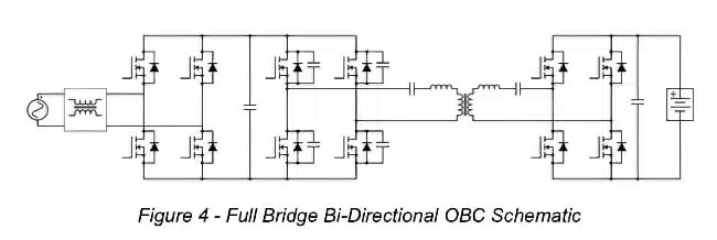
LLC and CLLC resonant converter topologies are widely adopted in the DC/DC stage of EV OBCs due to their ability to achieve high efficiency, soft-switching operation, and high-power density. These resonant converters typically operate at elevated switching frequencies, enabling compact magnetic designs while minimizing switching losses. As battery voltages and charging power levels continue to increase, particularly with the adoption of 800 V-class EV platforms, the DC/DC stage is subjected to higher electrical stresses. This places greater emphasis on the performance and reliability of passive components used in resonant tanks, snubber circuits, and filtering networks, where stable electrical characteristics are critical.
Architectural Similarities to AI Server Power Systems
With the shift toward higher-voltage power distribution, AI data centers are beginning to converge on power conversion architectures that have long been proven in EV OBCs. In both environments, electrical power needs to be converted from high-voltage AC mains to a regulated DC output while maintaining high efficiency and power density.
In EV OBCs, an isolated DC/DC stage—commonly implemented using LLC or CLLC resonant topologies converts a high-voltage DC bus from the PFC stage into a controlled battery charging voltage. Similarly, emerging AI server architectures distribute power at higher DC voltage levels and rely on DC/DC converter topologies located at the rack and board level to generate intermediate and point-of-load voltages for GPUs. In both cases, these DC/DC stages operate at elevated switching frequencies to achieve high power density and efficiency, placing demanding requirements on resonant components, snubber networks, and filtering elements.
These similarities between the two architectures lead to closely aligned component-level requirements across EV and AI power systems. High-voltage DC/DC stages in both environments demand passive components capable of withstanding sustained high AC voltages, high ripple currents, and elevated operating temperatures. As AI infrastructure moves toward continuous, high-utilization operation with power densities approaching those encountered in EV charging systems, the design practices and component technologies proven in EV OBC DC/DC applications provide a solid foundation for the next generation of AI server power architectures.
Why This Matters for Passive Components
As power architectures converge toward high-voltage, high-power DC/DC conversion, the electrical and thermal stresses imposed on passive components increase significantly, with important differences in duty cycle. EV OBCs are exposed to high electrical and thermal stress but only operate during the charging cycle. In contrast, AI server power systems must operate continuously, often at high utilization, to achieve, for extended service lifetimes.
In both environments, resonant capacitors used in LLC- and CLLC-based DC/DC stages are subjected to high-frequency AC voltages. These operating conditions produce substantial AC ripple current through the resonant capacitor, resulting in internal heating due to I²R losses and elevated component operating temperature. If not properly designed, sustained electrical and thermal stress can accelerate aging mechanisms and reduce effective lifetime.
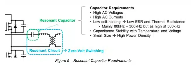
In AI data center environments, where 24/7 operation is expected and power density continues to increase, these effects become more pronounced. Under continuous high-voltage operation, the performance of the resonant capacitor directly influences converter efficiency, thermal stability, and long-term system reliability. As a result, passive component selection—particularly for resonant and snubber functions—becomes a critical design consideration.
Why C0G (NP0) MLCC Capacitors Matters in High Voltage DC/DC Conversion
Advantages of C0G in High Voltage Applications
C0G (NP0) Class 1 MLCC ceramic capacitor dielectrics offer a combination of electrical and reliability characteristics that make them well-suited for resonant capacitors used in high-voltage DC/DC conversion stages, including LLC- and CLLC-based architectures deployed in both automotive and AI infrastructure. In these converters, the resonant capacitor is subjected to large high-frequency AC voltage swing and elevated thermal loading, placing stringent requirements on dielectric stability, loss characteristics, and ripple-current handling capability.
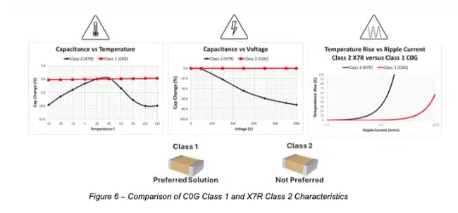
A primary advantage of C0G dielectrics is their negligible change in capacitance with applied DC or AC voltage. Unlike high-K ferroelectric dielectrics, C0G resonant capacitors maintain essentially constant capacitance across the operating voltage range, even under large AC voltages in resonant tanks. This stability helps preserve resonant frequency and operating characteristics, reducing sensitivity to operating point variation in high-voltage DC/DC stages. C0G capacitors also exhibit very low temperature coefficients of capacitance, typically on the order of ±30 ppm/°C, resulting in minimal capacitance drift over the full operating temperature range.
From a loss and reliability perspective, C0G dielectrics offer very low ESR, reducing I²R losses in the resonant capacitor under high AC ripple current conditions. Lower resistive losses limit self-heating and reduce the risk of thermal runaway under sustained operation. Combined with non-aging DC-BIAS characteristics and robust insulation performance, these attributes support improved long-term reliability of resonant capacitors, particularly in continuously operating environments such as AI data centers.
Technical overview of YAGEO’s high-voltage C0G MLCC portfolio
YAGEO’s C0G-based MLCC portfolio for high-voltage applications builds on their wider MLCC platform, which spans general-purpose, high-voltage, soft-termination, high-Q RF, high-reliability automotive, and low-inductance devices for compact, high-performance designs. Within this platform, the high-voltage C0G range targets demanding AI server, EV, and industrial power stages that require low-loss behaviour, excellent stability, and predictable capacitance under voltage and temperature stress.
Key technical attributes of the high-voltage C0G portfolio include:
- C0G/NP0 dielectric with near-zero temperature coefficient, negligible ageing, and excellent capacitance stability under bias for precise timing, resonance, and low-loss decoupling in 800 V power paths.
- High-voltage ratings that align with 800 V-class architectures and 1000 V-class components, enabling use on both primary and secondary sides of high-voltage DC/DC stages and in EMI/EMC filter networks.
- Low dielectric losses and high Q, supporting efficient high-frequency operation in PFC, resonant converters, and OBC-inspired topologies used in AI racks.
- Availability in SMD MLCC formats compatible with automated assembly and compact layouts, helping to minimize parasitics and loop inductance in high di/dt regions.
- Automotive and industrial qualification options (AEC-Q and extended screening) for platforms that must meet long-term reliability and harsh-environment requirements.
| Family | Dielectric / class | Typical voltage range | Typical temp range | Key characteristics | Typical applications |
|---|---|---|---|---|---|
| C0G MLCC | C0G / NPO, Class I | ~6.3 V to 3 kV DC (device dependent) | ~55 °C to +125 °C | Near-zero TCC, negligible ageing, very low loss, excellent stability vs. temperature and voltage. | Precision timing, resonant tanks, low-loss decoupling, EMI filters, high-voltage signal and measurement paths. |
| KC-Link | Class I, ultra-stable for WBG | ~25 V to 3 kV DC | Up to +150 °C (SiC/GaN focus) | Ultra-stable vs. frequency, temperature, and voltage; low ESR/ESL; optimized for high ripple and high dv/dt. | SiC/GaN power stages, snubbers, resonant converters (LLC), DC-link and DC blocking in high-frequency converters. |
| KC-Link with KONNEKT | KC-Link (Class I) + KONNEKT 3D packaging | ~500 V to 3 kV DC | Up to +150 °C | Stacked/3D package increasing capacitance density without extra PCB area; low parasitics and high current capability. | High-density DC-link, compact resonant tanks, high-power wireless charging, WBG-based power modules. |
| U2J MLCC | U2J, Class I | ~10 V to hundreds of volts DC (device dependent) | ~55 °C to +125 °C | Linear, negative TCC (around −750 ppm/°C) with low loss; more capacitance than C0G at the cost of larger TCC magnitude. | Precision circuits requiring predictable, monotonic capacitance change with temperature; tuned networks and sensor interfaces. |
These characteristics make YAGEO’s high-voltage C0G MLCCs suitable for critical roles such as resonant tank capacitors, snubber networks, HV DC-link decoupling on the primary side, and precision EMI filter elements in 800 V AI power distribution chains.
Easy to Design-in (E2Di)
To support customers with design-in activities, YAGEO Group offers a variety of tools and services to reduce design-in cycle time. These include tools such as our Y-SIM for simulation key MLCC characteristics as well as our Power Array Calculator that provides recommendations on part numbers and configurations for resonant solutions.
Source and References:
- https://iee.psu.edu/news/blog/why-ai-uses-so-much-energy-and-what-we-can-do-about
- https://www.iea.org/reports/energy-and-ai/energy-demand-from-ai
- Redefining-Data-Center-Power-GaN-and-SiC-Technologies-for-Next-Gen-800-VDC-Infrastructure.pdf
- https://www.ti.com/lit/ta/ssztdb4/ssztdb4.pdf?ts=1776942490642
- YAGEO Group MLCC and high-voltage C0G portfolio overview: https://www.yageo.com/en/Product/Overview


