


There are many different types of filters used in electronics. These filter types include low-pass, high-pass, band-pass, band-stop (band-rejection; notch), or all-pass. They are either active or passive.
Key Takeaways
- Passive Low Pass Filters allow low-frequency signals to pass while attenuating higher frequencies, making them essential in EMC work.
- These filters consist of passive components like resistors and capacitors, and they have no signal gain.
- Common designs include the L-type, π-filter, and T-filter, each with unique configurations for different applications.
- Effective use of Passive Low Pass Filters requires attention to layout, placement, and impedance matching to avoid performance issues.
- Parasitics and filter component behavior significantly influence their effectiveness in real-world applications.
In the realm of electromagnetic compatibility, the purpose of a filter is to establish a low-impedance path for RF current to return to the local source of energy, and/or to provide a high impedance to prevent RF currents from flowing on a cable. These so-called EMI filters are often used along with proper shielding to achieve electromagnetic compatibility (EMC) compliance for electrical/electronic products. Undoubtedly, the most useful filter type used in EMC work is the passive low-pass filter.
Passive filters are made up of passive components such as resistors, capacitors and inductors and have no amplifying elements (transistors, op-amps, etc) so have no signal gain, therefore their output level is always less than the input.
Filters are so named according to the frequency range of signals that they allow to pass through them, while blocking or “attenuating” the rest. The most commonly used filter designs (see also Fig.1.) are the:
- The Low Pass Filter – the low pass filter only allows low frequency signals from 0Hz to its cut-off frequency, ƒc point to pass while blocking those any higher.
- The High Pass Filter – the high pass filter only allows high frequency signals from its cut-off frequency, ƒc point and higher to infinity to pass through while blocking those any lower.
- The Band Pass Filter – the band pass filter allows signals falling within a certain frequency band setup between two points to pass through while blocking both the lower and higher frequencies either side of this frequency band.
- The Band Stop Filter – the band stop filter is reversal to the Band Pass Filter and allows signals passing both the lower and higher frequencies either side of the blocking frequency band.
Simple First-order passive filters (1st order) can be made by connecting together a single resistor and a single capacitor in series across an input signal, ( VIN ) with the output of the filter, ( VOUT ) taken from the junction of these two components (see Fig.2. for the first order low pass filter example).
Depending on which way around we connect the resistor and the capacitor with regards to the output signal determines the type of filter construction resulting in either a Low Pass Filter or a High Pass Filter.
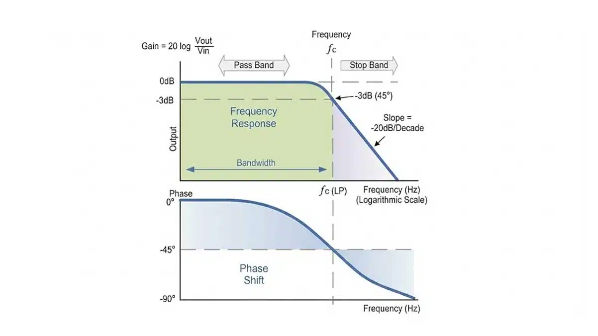
As the function of any filter is to allow signals of a given band of frequencies to pass unaltered while attenuating or weakening all others that are not wanted, we can define the amplitude response characteristics of an ideal filter by using an ideal frequency response curve of the four basic filter types as shown.
Ideal Filter Response Curves

Filters can be divided into two distinct types: active filters and passive filters. Active filters contain amplifying devices to increase signal strength while passive do not contain amplifying devices to strengthen the signal. As there are two passive components within a passive filter design the output signal has a smaller amplitude than its corresponding input signal, therefore passive RC filters attenuate the signal and have a gain of less than one, (unity).
A Low Pass Filter can be a combination of capacitance, inductance or resistance intended to produce high attenuation above a specified frequency and little or no attenuation below that frequency. The frequency at which the transition occurs is called the “cut-off” or “corner” frequency.
The simplest low pass filters consist of a resistor and capacitor but more sophisticated low pass filters have a combination of series inductors and parallel capacitors. In this tutorial we will look at the simplest type, a passive two component RC low pass filter.
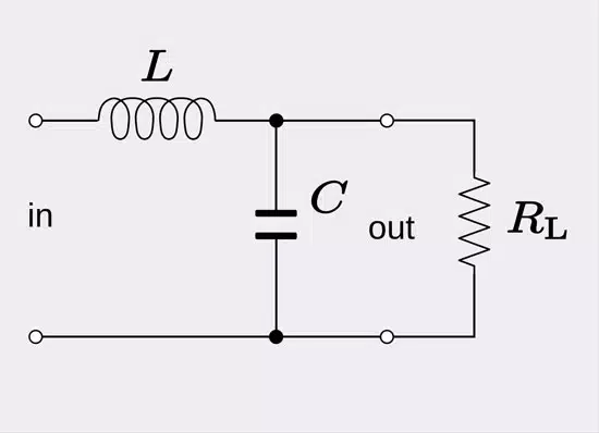
Passive Low Pass Filter
A Low Pass Filter is a circuit that can be designed to modify, reshape or reject all unwanted high frequencies of an electrical signal and accept or pass only those signals wanted by the circuits designer. In other words they “filter-out” unwanted signals and an ideal filter will separate and pass sinusoidal input signals based upon their frequency. In low frequency applications (up to 100kHz), passive filters are generally constructed using simple RC (Resistor-Capacitor) networks, while higher frequency filters (above 100kHz) are usually made from RLC (Resistor-Inductor-Capacitor) components.
RC Low-Pass Filter
A low-pass filter is a filter that allows signals with a frequency less than a particular cutoff frequency to pass through it and depresses all signals with frequencies beyond the cutoff frequency. The most basic type of low-pass filter type is called an RC filter, or an L-type filter because of its shape, with the resistive element in the signal line and capacitor placed from line to chassis, these two circuit elements form the shape of an inverted L.
In an RC low-pass filter, the cutoff frequency occurs at resonance, where the capacitive reactance (Xc) equals the resistance (Xc =1/2πfC, or 1/wC, w = 2πf). Sometimes the resistor is not required and just a single capacitor placed across a line to reference ground without a resistor installed may be all that is required to suppress any unwanted noise. A device that presents the circuit with a high AC impedance, while at the same time not affecting signal quality can be used in situations where the voltage drop across the series resistor cannot be tolerated. This device is called a ferrite bead. In addition to their frequency limitation, ferrites can also become easily saturated when there is too much DC current present in the circuit. Ferrites are ineffective if they are saturated and if DC current is too high, using a ferrite as an element in the low-pass may not be an option. Also, depending on how high the impedance is of the source or load requiring filtering, ferrites may not work because they are considered low-impedance and won’t work if circuit impedance is higher than their impedance.
Basic Filter Topologies
Besides the L-type passive filter there are a couple of other basic filter configurations. These multi-element filters are useful in situations where the range of frequencies involved is too large and impossible for a one component filter to fully attenuate successfully or the signal is too high in amplitude and that one filter element does not provide enough attenuation. Adding a second reactive component will increase the roll off to 12 dB/octave or 40 dB/decade. These types of filters are called various names such as double-pole, two-stage, two-element, or second-order filters. Filters with three reactive components will provide 18 dB/octave or 60 dB/decade attenuation. Four reactive component filters will provide 24 dB/octave or 80 dB/decade attenuation and so on.
Also, different filter shapes are used depending on source and load impedances of the circuit requiring filtering. These different types are used for impedance mismatching between circuit source and load input and output impedances and filter input and output impedances. Like the L-type filter, these other two types are both are named after their visual shapes on circuit diagrams. The first is the π-filter and the second is the T-filter low-pass filter.
Π Filter
The π low-pass filter looks like the Greek letter π. It has a capacitor from the line to be filtered to return, an in-circuit series element (resistor, inductor or ferrite), and then another capacitor from line to be filtered to return.
T Filter
The T low-pass filter looks like the letter T. It has an in-circuit element (resistor, inductor or ferrite) installed on the line to be filtered, a capacitor installed line to return, and then another in-circuit element (resistor, inductor, or ferrite).
Impedance Mismatching
As eluded to earlier, both source and load impedances must be considered in selecting the proper filter configuration (L, π, or T). If you are trying to install a low-pass filter into a circuit in order to suppress unwanted emissions and determine that it is not solving the problem then be sure to check that an impedance mis-match exists. A high-impedance series component should face a low-impedance (i.e. capacitor) and vice versa. You may be asking yourself “What is considered low-impedance and what is considered high-impedance?” In general, impedances of less than 100 Ω are considered low and impedances greater than about 100Ω are considered high.
Selection of the cut-off frequency (fco)
It is important to also ensure that by adding a filter’s impedance to circuit that it does not in turn create a signal integrity problem. In order to ensure this does not happen, be sure to select a cut-off frequency for the filter that does not also attenuate the intended signals used in the circuit. In order to prevent this issue from occurring, try to maintain at least the 5th harmonic of the intended signal (10th harmonic is ideal).
Differential Mode (DM) and Common Mode (CM) Noise Currents
DM signal currents are those out-of-phase currents which transmit intended data whereas CM signal currents are in-phase deliver no valuable data what-so-ever. Although they are much lower in amplitude than DM currents, CM currents are the main causes of regulatory radiated and conducted emissions testing issues.
In a perfect world, DM signals move along one side of a circuit track, and an equal and opposite DM signal moves back on the other side of the track. In order to prevent DM to CM conversion to occur, PCB layout must be perfect and no circuit discontinuities can exist. This ensures that complete canceling of the DM signals occur and no CM current is developed.
If suppression of DM noise is required then placing capacitors across the outgoing and return lines and/or an inductor in series with either outgoing or return line can be employed. This is called DM filtering. If installing a DM filter does not solve the noise problem, then the source of emissions may instead be CM noise.
CM signals are signals that exist in both outbound and return tracks of a circuit. Because they are in-phase, they do not cancel each other but add up substantially enough to cause EMI issues. Because CM noise is present line-to-ground. CM filtering often involves placing capacitors across each signal line to ground reference. and sometimes also using a CM inductor in the circuit. Any CM inductors placed into the circuit only act on the CM signals that are present, they do not affect the DM signals. If installing a CM filter does not solve the noise problem then the source of emissions may instead be DM noise.
Parasitics
When attempting to utilize a low-pass filter for EMI suppression it is imperative to also consider the non-ideal behavior of the components which make up the filter. Actual passive filter components such as a capacitor also contains some inductance and an inductor contains some capacitance. These parasitic elements of capacitors and inductors limit their useful bandwidth. For example, the reactance of a capacitor decreases until it reaches its self-resonant frequency as frequency increases. Above its self-resonant frequency point the capacitor becomes inductive and it acts like an inductor because of the parasitic inductance found in its metal plates. A similar situation occurs in inductors. These parasitic effects are greater in leaded types of capacitors and inductors than with the surface mount technology (SMT) types that have almost no lead length.
Layout and Placement Concerns
Proper layout and placement can become the critical factor when attempting to effectively utilize passive low-pass filters for EMI suppression. Longer than necessary trace lengths add extra inductance and impedance which compromise the effectiveness of the filter similar to what occurs as described above regarding parasitics. It is therefore crucial to keep connections short. This means placing filter components as close as possible to the circuit to be filtered and not overlooking the length of the return trace. Locating the filter some obscure location far away from the offending signal source is not ideal in most situations.
In addition to keeping connections short, be observant of trace or wire routing that permits too much capacitive and inductive coupling to other noisy signal or traces. To prevent this crosstalk issue from occurring, place filter components right at the entry connector (I/O and power inputs). Placement of a filter deeper inside a circuit or system is just asking for trouble. When proper separation is not maintained, input and output sections are bypassed and the filter is no longer effective. As with a lot of problems encountered in EMC design and troubleshooting, do not rely on ground as being the ultimate zero-ohm impedance path and sink for noise. It is far better to understand the path of current flow and to keep loop areas small.
Conclusion
Low-pass filters are the most widely used type of filters in EMC work. There are several different configurations to choose from depending on several factors including frequency of the intended signals, source and load impedances, and common or differential mode noise sources present in the circuit. Factors that render low-pass filters ineffective include the non-ideal behavior of passive components, parasitic circuit elements, too much DC current present in circuits that use ferrites, using a filter with too low of a cut-off frequency thereby severely attenuating desired signals, and poor layout and placement.
Further references:
- Basic Filter Circuits Explained
- Five Key Filter Specifications
- Filter Q Factor Explained
- Filter Bandwidth Explained
- Filter Poles and Zeros Explained
FAQ about Passive Low Pass Filters
A passive low pass filter is an RC, LC or RLC network made only from passive components that provides a low-impedance path for high-frequency RF noise back to its source while allowing low-frequency or DC signals to pass with minimal attenuation, so it is widely used for EMC compliance of electronic products.
An RC low pass filter typically places a resistor in series with the signal line and a capacitor from the line to return, forming an L-shape network that passes frequencies below the cutoff frequency and attenuates higher frequencies as the capacitor shunts RF current to ground.
The cutoff frequency of a simple RC low pass filter occurs where the capacitive reactance equals the series resistance, which is given by the condition , and above this frequency the output amplitude starts to roll off.
Ferrite beads can replace the series resistor in a low pass EMI filter when a high AC impedance element is needed that does not cause unacceptable DC voltage drop, but they must not be used in circuits with excessive DC current that would saturate the ferrite core.
L-type filters use one series and one shunt reactive element, π-filters place a shunt capacitor before and after a series element, and T-filters use two series elements with a shunt capacitor between them to achieve steeper attenuation or better impedance matching over wider frequency ranges.
Proper matching of source and load impedances to the filter, such as facing high-impedance series elements toward low-impedance shunt elements, is essential because impedance mismatches can drastically reduce attenuation and make an otherwise correct topology ineffective.
The cutoff frequency should be set high enough to avoid attenuating the useful signal, typically above at least the fifth harmonic and ideally the tenth harmonic of the fastest intended signal component, so that only unwanted RF noise is filtered out.
Differential mode noise consists of equal and opposite currents flowing in the forward and return conductors and carries useful data, while common mode noise consists of in-phase currents on both conductors relative to ground that add and typically cause conducted and radiated EMI issues.
Differential mode noise can be reduced using capacitors across the line pair and series inductors in one conductor, whereas common mode noise is usually suppressed by capacitors from each line to ground and by common mode chokes that act only on in-phase currents.
Real capacitors include parasitic inductance that leads to a self-resonant frequency above which they become inductive, and inductors include parasitic capacitance, so these non-ideal effects limit the effective bandwidth and can even create unwanted resonances in EMI filters.
Long traces add extra inductance and open large loop areas that reduce attenuation and allow coupling, so low pass filter components must be placed close to connectors or noise sources with short, tight return paths to prevent bypassing of the filter.
Typical causes include using an inappropriate topology for the source and load impedance, selecting a cutoff frequency that also attenuates useful signals, ignoring parasitic component behavior, saturating ferrites with DC current, and poor PCB placement or routing.
How to Design a Passive Low Pass EMI Filter
- Define signal bandwidth and EMI requirements
Start by identifying the intended signal type, its maximum fundamental frequency, and relevant regulatory EMI limits so that the low pass filter can be optimized for the real system constraints. Ensure the future cutoff frequency will be high enough to avoid degrading the data or power waveform while still attenuating the unwanted RF noise components above the emission bands of interest.
- Select suitable low pass filter topology
Choose between a simple L-type RC or LC filter for narrowband or low-frequency applications and π or T networks when steeper roll-off, higher attenuation or better impedance transformation is required. Consider that adding more reactive elements increases the filter order and steepens the attenuation slope, for example by about 12 dB per octave for second-order low pass designs.
- Match filter topology to source and load impedances
Evaluate the effective source and load impedances of the circuit, treating values below roughly 100 ohms as low impedance and values above this as high impedance from an EMI filter perspective. Orient series and shunt elements so that high-impedance elements face low-impedance nodes and vice versa to avoid severe impedance mismatches that would reduce real-world attenuation.
- Calculate the cutoff frequency and component values
For a simple RC low pass filter, compute the cutoff frequency where the reactance of the capacitor equals the series resistance, and choose values that keep the cutoff above at least the fifth harmonic of the highest useful signal. In higher-frequency or more demanding EMI applications, use LC or RLC combinations and verify the resulting transfer function to ensure that the filter provides adequate attenuation in the problematic bands.
- Choose between resistors, inductors and ferrites
Decide whether the series element should be a resistor, inductor or ferrite bead by considering allowable voltage drop, desired insertion loss at low frequency, and the DC current that might saturate magnetic components. Use ferrite beads when a frequency-dependent impedance is required without significant DC loss, but avoid them in high DC current paths and in circuits where the system impedance is higher than the ferrite impedance.
- Address differential mode and common mode noise paths
Analyze whether the dominant EMI mechanism is differential mode noise between conductors or common mode noise relative to ground, as each requires a different filter configuration to achieve compliance. Apply capacitors across line pairs and series inductors for differential mode suppression, and combine line-to-ground capacitors with common mode chokes when common mode currents dominate emissions.
- Account for parasitic behavior and self-resonance
Check component datasheets for self-resonant frequency, equivalent series inductance and equivalent series resistance to ensure that capacitors and inductors behave as intended over the relevant EMI spectrum. Prefer surface-mount parts with short leads to minimize parasitic inductance and capacitance, which otherwise can shift resonance points and degrade the stopband performance of the filter.
- Optimize PCB layout and component placement
Place low pass filter components as close as possible to connectors or noise sources, minimize trace lengths, and keep return paths short to avoid extra inductance and loop areas that can reduce attenuation. Prevent capacitive and inductive coupling around the filter by separating input and output traces and avoiding routing that allows high-frequency signals to bypass the filter network.
- Verify EMI performance and iterate the design
Test the filtered system using conducted and radiated emissions measurements to confirm that the low pass filter meets the required standards without introducing signal integrity issues. If limits are not met, revisit topology, impedance matching, cutoff frequency and layout, and identify whether unresolved issues are due to unaddressed common mode or differential mode noise sources.
References
- Archambeault, PCB Design for Real-World EMI Control, Kluwer Academic Publishers, 2002
- Frenzel, Jr., Principals of Electronic Communications Systems, Fourth Edition, McGraw-Hill, 2016
- André & Wyatt, EMI Troubleshooting Cookbook for Product Designers, Scitech Publishing, 2014.
- Montrose, EMC Made Simple, Printed Circuit Board and System Design, Montrose Compliance Services, Inc., 2014
- Armstrong, “EMC Filters Guide,” Interference Technology, 2017
- Montrose, Printed Circuit Board Design Techniques for EMC Compliance – A Handbook for Designers, 2nd Edition, 2000.