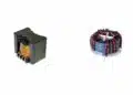
This post is based on edited tutorial video by Sam Ben-Yaakov that provides an educational content about power inductor design fundamentals and explains why power inductors use a ferrite cores with a gap.
Power inductors built around a gapped ferrite core are one of the most common building blocks in switch‑mode power supplies, PFC stages, DC‑DC converters and filter chokes. This article explains, from first principles, why designers choose ferrite, why a gap is introduced, and how the gap length is determined — based on a tutorial by Prof. Sam Ben‑Yaakov.
Key Takeaways
- Power inductors use a ferrite core with a gap to achieve smaller size and prevent saturation.
- Ferrite provides high permeability, while the air gap allows designers to manage inductance and control AC flux swings.
- Designers must size the gap to meet saturation and core loss requirements effectively.
- Both low-permeability powder cores and ferrite cores with gaps offer unique advantages for different frequency ranges.
- Understanding the interaction of core properties helps engineers choose the right inductor type based on application needs.
Why a ferrite core in the first place
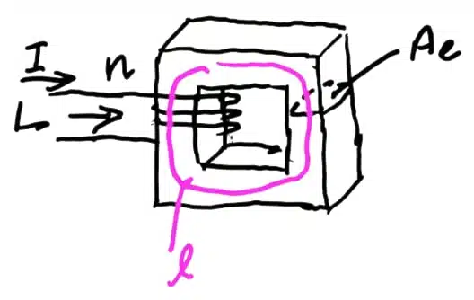
The starting point is the basic definition of inductance:
Combining this with , and Ampère’s law gives the classical expression:
The inductance is linearly proportional to the relative permeability . A ferrite such as Ferroxcube 3C98 offers a relative permeability on the order of 2000–4000, versus 1 for air. For a given target inductance, higher allows a smaller cross‑section or fewer turns .
In practice this means one thing: the main purpose of the ferrite is to shrink the physical size of the inductor.
Saturation and core losses
High permeability comes with two hard limits on the magnetic flux density :
- Saturation. Ferrite materials saturate roughly between 300 and 400 mT. Above that level the B–H slope collapses, permeability drops and the inductor stops behaving as an inductor.
- Core losses. AC swings of dissipate energy. Loss per unit volume grows strongly with the peak AC flux density and with frequency.
Starting again from Ampère’s law and
This expression reveals the tension in the design: high is desirable for size, but it directly drives upward for a given current. When current — and therefore stored energy — is high, a lower effective permeability is required to keep within safe limits.
Option 1: low‑permeability powder cores
One way to reduce effective permeability is to use powder or distributed‑gap materials such as Kool Mµ from Magnetics, available with relative permeabilities as low as 20–50. These materials are produced by mixing ferromagnetic particles with an inert binder, creating a distributed air gap throughout the volume.
The limitation is frequency. Powder cores typically perform well up to around 50–100 kHz. At a few hundred kHz, and certainly at 1 MHz, their losses become prohibitive when the ripple component of B is significant. For high‑frequency converters another solution is needed.
Option 2: a ferrite core with a discrete air gap
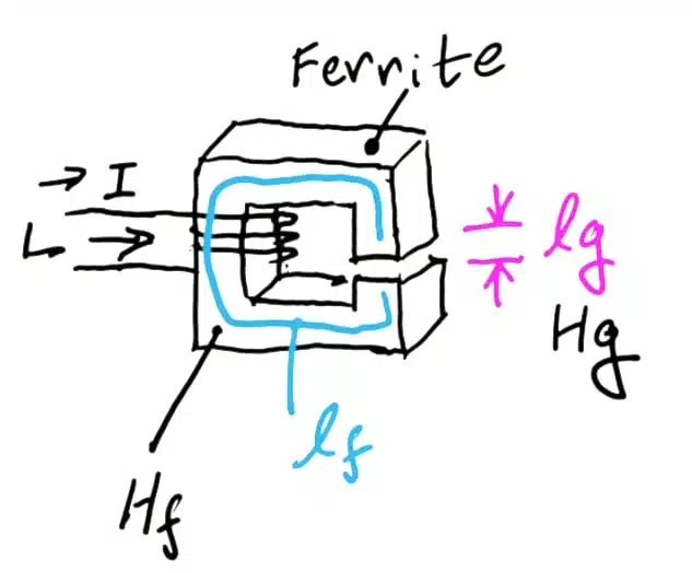
This is the classical topology of modern SMPS inductors. Applying Ampère’s law along a path that crosses both the ferrite and the gap:
Substituting for each region and solving for B:
Because is large, the first term in the denominator is usually much smaller than the second, even though the ferrite path is geometrically much longer than the gap. A useful approximation is therefore:
The gap length directly sets the peak flux density: the longer the gap, the lower BBB, and the further the core is kept from saturation and from excessive AC losses.
Effective permeability of a gapped core
Plugging the approximation above into and rearranging against the total magnetic path length yields an expression that mirrors the ungapped case, but with an effective permeability:
A core with a 100 mm magnetic path length and a 1 mm gap therefore behaves as if it had a relative permeability of around 100. By selecting the gap, the designer effectively dials in the permeability needed for the application, decoupling it from the raw material property of the ferrite.
Rod inductors follow the same rules
Rod‑core inductors, with their open magnetic structure, can be viewed as an extreme case of a very large air gap. The flux spreads outside the rod, so the closed‑form equations above no longer apply cleanly, but the physical argument is identical: the ferrite rod raises effective permeability above free air, reducing the required turns count or cross‑section, while the open return path prevents saturation at high currents.
Design‑in notes for engineers
- Choose ferrite when switching frequencies are high (hundreds of kHz to MHz) and core losses dominate the thermal budget.
- Choose powder / distributed‑gap cores such as Kool Mµ for lower‑frequency, high‑ripple or PFC chokes where gradual saturation and mechanical simplicity are advantageous.
- Size the gap for two independent constraints: keep below saturation at , and keep low enough that volumetric core losses remain within the allowable temperature rise.
- Remember the trade‑off: widening the gap lowers B and inductance, so more turns (and therefore more copper loss and winding space) are required to restore the target L.
- Fringing flux around the gap increases winding losses; keep windings away from the gap region or use distributed gaps for high‑frequency designs.
Exact material data (saturation , loss curves, temperature dependence) should always be taken from the manufacturer datasheet for the specific ferrite grade or powder mix being considered.
Conclusion
A ferrite core with a discrete air gap is not a compromise — it is a deliberate way to combine two desirable properties in a single magnetic component. The ferrite provides the high permeability needed to keep the inductor compact and efficient at high switching frequencies, while the gap sets an effective, lower permeability that prevents saturation and controls AC flux swings.
In practice, the gap length becomes the main design knob: it defines , the effective permeability , and indirectly the number of turns required to reach the target inductance. Understanding this interaction allows power‑electronics engineers to choose between gapped ferrite, distributed‑gap powder cores such as Kool Mµ, or open rod structures based on frequency, ripple and energy‑storage requirements rather than on rules of thumb.
FAQ
Ferrite offers a high relative permeability (typically 2000–4000), which dramatically increases inductance for a given number of turns and cross‑section. This allows designers to build physically smaller inductors for the same inductance value, which is critical in modern switch‑mode power supplies.
Without a gap, a high‑permeability ferrite saturates at relatively low currents because the flux density B is directly proportional to permeability. Introducing a small air gap reduces the effective permeability and therefore the peak B, keeping the core safely below its saturation limit (around 300–400 mT for typical ferrites) and limiting AC core losses.
A longer gap lowers both the peak flux density and the inductance. As a rule of thumb, the effective permeability of a gapped core is approximately the ratio of the ferrite path length to the gap length, so doubling the gap roughly halves the effective permeability and the inductance per turn squared.
Powder cores with a distributed air gap, such as Magnetics Kool Mµ, are well suited to lower switching frequencies (typically up to 50–100 kHz) and applications with high DC bias and soft saturation characteristics, such as PFC chokes. For higher frequencies in the hundreds of kHz to MHz range, gapped ferrite usually offers significantly lower losses.
Yes, conceptually. A rod inductor can be viewed as a ferrite core with a very large open air gap. The rod still raises the effective permeability above free air, reducing the required turns, while the open flux return path prevents hard saturation — at the cost of higher external stray field and EMI considerations.
Core losses are driven mainly by the peak AC flux density and the switching frequency. Hysteresis and eddy‑current losses grow strongly with both, so the gap must be sized not only to avoid DC saturation but also to keep the AC component of B low enough to respect the allowable temperature rise of the core material.
Source
This article is based on the tutorial “Power Electronics Fundamentals: Why ferrite and a gap in power inductors?” by Prof. Sam Ben‑Yaakov, published on his YouTube channel. Material references (Ferroxcube 3C98 ferrite and Magnetics Kool Mµ powder cores) are mentioned as given in the original presentation.
References
- Sam Ben‑Yaakov – Power Electronics Fundamentals: Why ferrite and a gap in power inductors? (YouTube)
- Ferroxcube 3C98 ferrite material overview
- Magnetics Kool Mµ powder core family