


Digital isolators have become a standard building block wherever sensitive low‑voltage control electronics need to communicate across noisy, high‑voltage domains.
Würth Elektronik is now extending its portfolio with 2‑channel bidirectional isolators aimed specifically at I²C interfaces, offering an alternative to traditional optocoupler‑based solutions in industrial, automotive and IoT designs. For engineers used to working with isolated DC/DC converters, shunt resistors, filters and transient protection, these parts provide a complementary way to protect signal paths and ensure reliable bus communication.
Key features and benefits
- Bidirectional I²C support: The WPME‑CDI2C family is designed for I²C, supporting bidirectional communication on the serial data line and either bidirectional or unidirectional operation on the serial clock line, depending on the variant.
- Up to 2 MHz transfer rate: Data rates up to 2 MHz cover the majority of standard‑ and fast‑mode I²C applications, including many sensor and monitoring interfaces in power and automotive electronics.
- Galvanic isolation for safety and EMC: With an isolation rating of up to 3750 VRMS according to UL 1577 and basic insulation according to IEC 60747‑17, the devices provide a defined isolation barrier between domains with different ground potentials.
- High common‑mode transient immunity (CMTI): A specified CMTI of ±150 kV/µs helps maintain data integrity even when fast dV/dt events occur in power stages, such as switching edges in half‑bridges or PFC circuits.
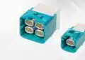
- SOIC‑8NB package with pin compatibility: The isolators come in a narrow‑body SOIC‑8 package that is pin‑compatible with common I²C isolators, simplifying second‑sourcing and drop‑in replacement from a PCB layout perspective
- Complementary to passive protection: By combining galvanic isolation with appropriate TVS diodes, filters and surge arresters, designers can build robust signal chains suitable for harsh industrial and automotive environments.
Typical applications
I²C is widely used as an internal “housekeeping” bus in power, automotive and industrial systems. Digital isolators targeted at this interface can help separate noisy or high‑voltage domains from sensitive control electronics.
IoT and consumer electronics
- Sensor nodes and local sensor hubs, where an isolated I²C bus connects sensors on a different ground potential to the main microcontroller or gateway.
- Display and user interface modules, especially when the UI is mounted on floating or shielded metal parts that might be at a different potential.
Industrial automation and power systems
- Sensor networks and monitoring systems in factory automation, where field‑side sensor boards sit close to high‑power equipment while controllers remain in a protected low‑voltage domain.
- Motor control and inverter systems using I²C for configuration, temperature monitoring or auxiliary power stage supervision, adjacent to isolated gate drivers and isolated DC link measurement circuits.
- Isolated data acquisition front ends, where shunt resistors, current transformers or hall sensors feed ADCs whose I²C bus is isolated back to a central controller.
Automotive and mobility
- Battery management systems (BMS), where I²C is used for temperature and voltage monitoring or for communication between stacked modules and a central controller.
- Engine and drivetrain control units, where isolated I²C links help bridge between noisy power stages and sensitive logic, complementing existing isolation in gate drivers and sensor interfaces.
In many of these use cases, the isolator sits alongside passive EMI filters, surge protection and common‑mode chokes to form a complete protection and isolation concept around the I²C lines.
Technical highlights
The WPME‑CDI2C devices address typical challenges of isolating an I²C bus while maintaining compatibility with existing designs.
Isolation and safety ratings
- Isolation voltage up to 3750 VRMS according to UL 1577.
- Basic insulation rating according to IEC 60747‑17 (VDE 0884‑17).
- Defined test methods and insulation classes make it easier for safety engineers to integrate the isolator into system‑level insulation coordination, alongside isolated power supplies and reinforced creepage distances on the PCB.
In practice, these ratings mean the component can form part of a basic insulation barrier between low‑voltage control electronics and higher‑voltage domains, provided that PCB creepage/clearance and the rest of the insulation system (connectors, transformers, shunt placement) are designed accordingly.
Signal performance and noise immunity
- Data rate up to 2 MHz, suitable for standard‑mode (100 kHz), fast‑mode (400 kHz) and many fast‑mode plus applications, depending on the actual bus timing requirements.
- Common‑mode transient immunity (CMTI) of ±150 kV/µs to ensure correct operation during fast switching events and ground potential shifts near power stages.
High CMTI is especially relevant where I²C lines run in parallel with switching nodes or near high dV/dt nodes (e.g., half‑bridge outputs), reducing the risk that transient events corrupt bus communication.
Package and pinout
- SOIC‑8NB package, pin‑compatible with standard I²C isolators commonly used in the market.
- Two device variants:
- Bidirectional SDA and bidirectional SCL.
- Bidirectional SDA and unidirectional SCL.
Selecting between these variants lets designers align the isolator’s clock behaviour with their specific I²C topology, for example where clock stretching is required or where the clock is strictly master‑driven.
Position in the component ecosystem
Although digital isolators are active components, they work closely with passive parts:
- Series resistors and RC filters on SDA/SCL lines shape edges and limit ringing, helping both EMC and signal integrity.
- Common‑mode chokes on the I²C lines can further attenuate conducted noise, especially in long cable runs.
- TVS diodes and other surge arresters provide additional protection against ESD and surge events at the isolated interface.
From a purchasing and design‑in perspective, the WPME‑CDI2C complements existing portfolios of isolated DC/DC converters, isolation transformers and EMI filters.
Overview of key parameters
| Parameter | Typical value / description |
|---|---|
| Interface type | 2‑channel I²C (SDA + SCL) |
| Data rate | Up to 2 MHz |
| Isolation voltage | Up to 3750 VRMS (UL 1577) |
| Insulation class | Basic insulation (IEC 60747‑17 / VDE 0884‑17) |
| CMTI | ±150 kV/µs |
| Package | SOIC‑8 narrow body |
| Variants | SDA + SCL both bidirectional; SDA bidirectional, SCL unidirectional |
All exact values and tolerances are according to the manufacturer datasheet and safety documentation.
Design‑in notes for engineers
While the WPME‑CDI2C devices target I²C specifically, integrating them into a robust design requires careful consideration of the surrounding passive network, PCB layout and system‑level insulation.
- Check I²C timing and mode: Confirm that your I²C speed and timing (standard, fast or fast‑mode plus) are compatible with the isolator’s propagation delays and 2 MHz data rate limit, especially if clock stretching or long cable runs are involved.
- Select the right variant: Choose the variant with bidirectional SCL if your architecture relies on clock stretching, or the SDA‑bidirectional/SCL‑unidirectional type for simpler, master‑driven buses without slave clock manipulation.
- Coordinate with isolated power: If the isolated I²C domain is powered by an isolated DC/DC converter or transformer‑based supply, ensure that isolation ratings and creepage/clearance of all elements (isolator, transformer, connectors, PCB slots) are consistent with the required safety class.
- Add appropriate line protection: Complement the isolator with ESD and surge protection devices (e.g., TVS diodes) and, where needed, common‑mode chokes and RC filters to meet EMC requirements and protect the device against transients at the interface.
- Pay attention to layout: Keep the isolation barrier clear on the PCB, with adequate creepage and clearance distances on the board according to the system’s working voltage and pollution degree, similar to practices used for isolated gate drivers and isolated DC/DC converters.
- Consider bus capacitance and pull‑ups: As with any I²C design, total bus capacitance and pull‑up resistor values need to be reviewed; the isolator adds its own capacitance and propagation delay, so pull‑up strength and rise times may need adjustment for reliable operation.
- Plan for test and diagnostics: In safety‑critical systems, consider adding test points or self‑test routines that verify communication across the isolated I²C interface during production test and at power‑up.
For engineers already specifying shunt resistors, current sensors, EMI filters and surge protection devices, these digital isolators offer a complementary way to structure the signal and power partitions of the system, aligning functional safety and EMC goals with a clear division between primary and secondary circuits.
Source
This article is based on an official Würth Elektronik press release and associated product information, adapted and extended to provide additional design and application context for engineers working with isolated interfaces and supporting passive components.