Passive Components Blog
No Result
View All Result
  • Home
  • NewsFilter
    • All
    • Aerospace & Defence
    • Antenna
    • Applications
    • Automotive
    • Capacitors
    • Circuit Protection Devices
    • electro-mechanical news
    • Filters
    • Fuses
    • Inductors
    • Industrial
    • Integrated Passives
    • inter-connect news
    • Market & Supply Chain
    • Market Insights
    • Medical
    • Modelling and Simulation
    • New Materials & Supply
    • New Technologies
    • Non-linear Passives
    • Oscillators
    • Passive Sensors News
    • Resistors
    • RF & Microwave
    • Telecommunication
    • Weekly Digest

    Samsung Releases Automotive Molded 2220 1kV C0G MLCC

    How to Select Ferrite Bead for Filtering in Buck Boost Converter

    VINATech Offers Smallest 100µF Al-Hybrid Capacitor

    Vishay Unveils SMD 1200V PTC Thermistors in Compact Size

    Power Inductors Future: Minimal Losses and Compact Designs

    Bourns Unveils Automotive 3 Watt Gate Driver Transformer

    Murata Opens EMC Test Lab in Nuremberg to Enhance Automotive Support

    Percolation Phenomenon: Degradation of Molded Power Inductors in DC/DC Converters

    Molex Acquires Smiths Interconnect

    Trending Tags

    • Ripple Current
    • RF
    • Leakage Current
    • Tantalum vs Ceramic
    • Snubber
    • Low ESR
    • Feedthrough
    • Derating
    • Dielectric Constant
    • New Products
    • Market Reports
  • VideoFilter
    • All
    • Antenna videos
    • Capacitor videos
    • Circuit Protection Video
    • Filter videos
    • Fuse videos
    • Inductor videos
    • Inter-Connect Video
    • Non-linear passives videos
    • Oscillator videos
    • Passive sensors videos
    • Resistor videos

    How to Select Ferrite Bead for Filtering in Buck Boost Converter

    Power Inductors Future: Minimal Losses and Compact Designs

    Percolation Phenomenon: Degradation of Molded Power Inductors in DC/DC Converters

    Connector PCB Design Challenges

    Efficient Power Converters: Duty Cycle vs Conduction Losses

    Ripple Steering in Coupled Inductors: SEPIC Case

    SEPIC Converter with Coupled and Uncoupled Inductors

    Coupled Inductors in SEPIC versus Flyback Converters

    Non-Linear MLCC Class II Capacitor Measurements Challenges

    Trending Tags

    • Capacitors explained
    • Inductors explained
    • Resistors explained
    • Filters explained
    • Application Video Guidelines
    • EMC
    • New Products
    • Ripple Current
    • Simulation
    • Tantalum vs Ceramic
  • Knowledge Blog
  • Suppliers
    • Who is Who
  • PCNS
    • PCNS 2025
    • PCNS 2023
    • PCNS 2021
    • PCNS 2019
    • PCNS 2017
  • Events
No Result
View All Result
Passive Components Blog
No Result
View All Result

Board-to-Board Connectors

20.3.2025
Reading Time: 3 mins read
A A

Board-To-Board connectors (BTB) were originally used primarily at Level 2. Recent developments have extended their application to Level 3. BTB connectors come in two styles, one-piece and two-piece.

One-piece connectors were developed first with the two-piece style being developed as pin counts increased and centerlines decreased, that is for High-Density, HD, applications.

RelatedPosts

Polymer Materials and Processing

What is RF Connector

Connector Materials and Processes

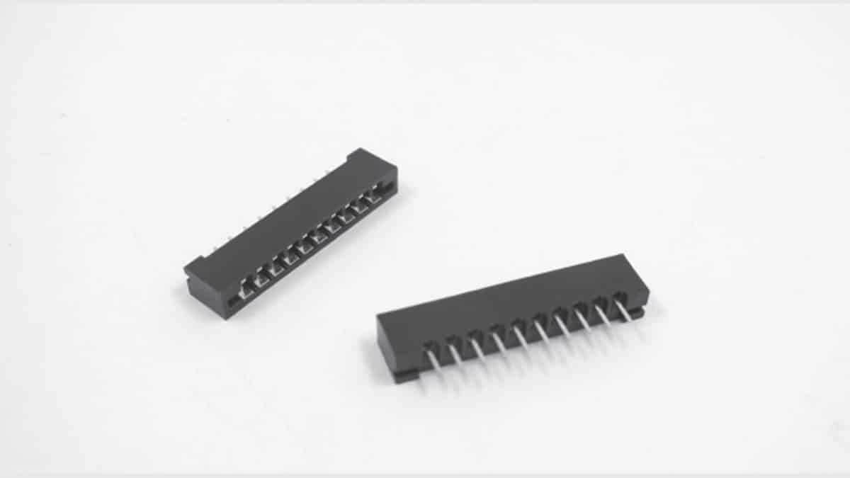
A one-piece system consists of a receptacle connector, mounted on the motherboard that accepts a daughterboard with contact pads on the edge of the PWB, hence the name “card edge” connector, Figure 2.125. The major advantage of one-piece connectors is cost; only a receptacle connector is needed. Limitations include the necessity to have contact pads on the board edge and, more importantly, tolerance control.

The tolerance issues include variations in PWB thickness and bow or warp of the PWB, tolerances which vary with board size. Card edge connectors use one or two rows of cantilever beam contacts to mate to one or both sides of a PWB. The design of cantilever beam contacts must address these tolerance variations, which impact on contact force, in order to ensure meeting maximum and minimum contact force requirements. The minimum normal force requirement is intended to ensure mechanical stability of the separable interface. The maximum requirement addresses both connector mating force and durability concerns. One-piece BTB connectors are generally through hole mounted to the motherboard by soldering or compliant press-in connections. Contact springs are generally phosphor bronze with tin or gold over nickel finishes depending on the application. Connector housing materials include polyester, PPS and, for high pin counts, LCP. High pin count card edge connectors with Low or Zero Insertion Force, LIF/ZIF, designs have been developed.

Fig. 2.125: Edge card connector
Fig. 2.126: ZIF connectors WR-FPC

Two-piece BTB connectors have superior tolerance control due to the control of separable interface tolerances available with stamped and formed contact in the receptacle and plug housings. This advantage, of course, comes at a cost. As noted, two-piece connectors were initially developed to address tolerance issues in high density connectors, but increasing electrical performance requirements and the proliferation of SMT applications have spurred further developments.

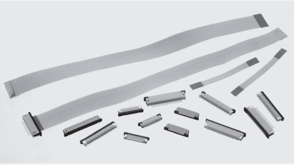
The advantages of two-piece BTB connectors with respect to HD applications are two fold. First, connectors with two to eight rows are possible, and, second, tighter centerlines can be realized (see a 0.8 mm itch example Figure 2.127).

Fig. 2.127: 0.8 mm pitch BTB connector

The advantages of two-piece BTB connectors with respect to enhanced electrical performance are also two fold. First, ground pins can be assigned to enhance impedance control in open pin field connectors and, second, ground planes can be incorporated to introduce Microstrip and Stripline impedance control.

Two-piece BTB connectors are more suitable for SMT applications due to the reduced contact forces, and tolerances, and the reduced mating forces that can be realized, which is an important requirement for SMT.

The same materials noted for one-piece BTB connectors are used, with the addition of beryllium copper as a contact spring material option. Contact spring designs are also different in that post receptacle designs with two or four receptacle contact beams replace the single cantilever beams typical of card edge BTB. This design difference is, of course, the reason for all the advantages of two-piece BTB discussed. The most common two-piece configuration has the pin contact half of the system mounted on the motherboard which mates to a right angle receptacle contact mounted on the daughter card. The termination to the PWBs may be by either soldering or compliant press-in technologies.

BTB connector variants are also used at Level 3. In most Level 2 BTB applications the daughter card plugs into the motherboard vertically. In Level 3 BTB the daughter cards may plug into the motherboard horizontally using right angle BTB connectors. This configuration is often called a mezzanine connector, often seen in computer/Telecom applications.

Related

Source: Wurth elektronik

Recent Posts

Connector PCB Design Challenges

3.10.2025
48
source: Samtec

Best Practices for Cable Management in High-Speed and High-Density Systems

4.9.2025
50

Non-Magnetic Interconnects

23.4.2025
27

Multi-Connectors Mating

20.3.2025
58

10 Tips for Ensuring Reliability of Discrete Wire Assemblies

20.2.2025
56

Polymer Materials and Processing

11.8.2025
60

Basic PCB Technology Overview

1.7.2025
24

What is RF Connector

17.12.2024
14

Creepage and Clearance of Connector

25.7.2025
24

Microwave Multi Line Connectors Mounting and Handling Precautions

11.8.2025
3

Upcoming Events

Oct 28
8:00 - 15:00 CET

Power Up Your Design: SN6507 and the Ready-to-Use Development Kit

Oct 30
11:00 - 12:00 CET

Space Ceramic Capacitors with Flexible Testing

Nov 4
10:00 - 11:00 PST

Design and Stability Analysis of GaN Power Amplifiers using Advanced Simulation Tools

View Calendar

Popular Posts

  • Buck Converter Design and Calculation

    0 shares
    Share 0 Tweet 0
  • Boost Converter Design and Calculation

    0 shares
    Share 0 Tweet 0
  • LLC Resonant Converter Design and Calculation

    0 shares
    Share 0 Tweet 0
  • Flyback Converter Design and Calculation

    0 shares
    Share 0 Tweet 0
  • Ripple Current and its Effects on the Performance of Capacitors

    3 shares
    Share 3 Tweet 0
  • What is a Dielectric Constant and DF of Plastic Materials?

    4 shares
    Share 4 Tweet 0
  • SEPIC Converter Design and Calculation

    0 shares
    Share 0 Tweet 0
  • MLCC and Ceramic Capacitors

    0 shares
    Share 0 Tweet 0
  • Dual Active Bridge (DAB) Topology

    0 shares
    Share 0 Tweet 0
  • Flying Capacitors

    0 shares
    Share 0 Tweet 0

Newsletter Subscription


Passive Components Blog

© EPCI - Leading Passive Components Educational and Information Site

  • Home
  • Privacy Policy
  • EPCI Membership & Advertisement
  • About

No Result
View All Result
  • Home
  • Knowledge Blog
  • PCNS

© EPCI - Leading Passive Components Educational and Information Site

This website uses cookies. By continuing to use this website you are giving consent to cookies being used. Visit our Privacy and Cookie Policy.
Go to mobile version