Passive Components Blog
No Result
View All Result
  • Home
  • News
    • All
    • Aerospace & Defence
    • Antenna
    • Applications
    • Automotive
    • Capacitors
    • Circuit Protection Devices
    • electro-mechanical news
    • Filters
    • Fuses
    • Inductors
    • Industrial
    • Integrated Passives
    • inter-connect news
    • Market & Supply Chain
    • Market Insights
    • Medical
    • Modelling and Simulation
    • New Materials & Supply
    • New Technologies
    • Non-linear Passives
    • Oscillators
    • Passive Sensors News
    • Resistors
    • RF & Microwave
    • Telecommunication
    • Weekly Digest

    Vishay Thin Film Chip Resistors Combine up to 50 GHz Operation with High Power Density

    Samsung Electro-Mechanics Secures KRW 1.0722 Trillion AI Server MLCC Supply Contract

    KYOCERA AVX Adds 0201 C0G RF MLCCs to KGU Ultra-Low-ESR Capacitor Series

    Vishay Extends High-Current Common-Mode Chokes with 30 A EMI Filtering up to 150 °C

    Bourns Copper-Electrode MOV Series Targets High-Energy Line Surge Protection

    Bourns Expands 12 mm SMD Incremental Encoder with Shaft-Length Options for Compact HMI Controls

    KEMET HRA X7R High-Reliability MLCCs Target Higher Capacitance in Defense and Aerospace Electronics

    B–H Curve-Based Inductor Modelling in LTspice: A Current-Dependent Magnetic Model

    Bourns UT-A Wirewound Power Resistors Target High-Temperature and Pulse-Load Applications

    Trending Tags

    • Ripple Current
    • RF
    • Leakage Current
    • Tantalum vs Ceramic
    • Snubber
    • Low ESR
    • Feedthrough
    • Derating
    • Dielectric Constant
    • New Products
    • Market Reports
  • Knowledge Blog
  • Dossiers
    • AI Hardware Dossier
    • Automotive Dossier
    • Industrial Robotics Dossier
    • Power Converter Dossier
    • Capacitor Dossier
    • Resistor Dossier
    • Inductor Dossier
    • Circuit Protection Dossier
  • Suppliers
    • Who is Who
  • PCNS
    • PCNS 2025
    • PCNS 2023
    • PCNS 2021
    • PCNS 2019
    • PCNS 2017
  • Events
  • Home
  • News
    • All
    • Aerospace & Defence
    • Antenna
    • Applications
    • Automotive
    • Capacitors
    • Circuit Protection Devices
    • electro-mechanical news
    • Filters
    • Fuses
    • Inductors
    • Industrial
    • Integrated Passives
    • inter-connect news
    • Market & Supply Chain
    • Market Insights
    • Medical
    • Modelling and Simulation
    • New Materials & Supply
    • New Technologies
    • Non-linear Passives
    • Oscillators
    • Passive Sensors News
    • Resistors
    • RF & Microwave
    • Telecommunication
    • Weekly Digest

    Vishay Thin Film Chip Resistors Combine up to 50 GHz Operation with High Power Density

    Samsung Electro-Mechanics Secures KRW 1.0722 Trillion AI Server MLCC Supply Contract

    KYOCERA AVX Adds 0201 C0G RF MLCCs to KGU Ultra-Low-ESR Capacitor Series

    Vishay Extends High-Current Common-Mode Chokes with 30 A EMI Filtering up to 150 °C

    Bourns Copper-Electrode MOV Series Targets High-Energy Line Surge Protection

    Bourns Expands 12 mm SMD Incremental Encoder with Shaft-Length Options for Compact HMI Controls

    KEMET HRA X7R High-Reliability MLCCs Target Higher Capacitance in Defense and Aerospace Electronics

    B–H Curve-Based Inductor Modelling in LTspice: A Current-Dependent Magnetic Model

    Bourns UT-A Wirewound Power Resistors Target High-Temperature and Pulse-Load Applications

    Trending Tags

    • Ripple Current
    • RF
    • Leakage Current
    • Tantalum vs Ceramic
    • Snubber
    • Low ESR
    • Feedthrough
    • Derating
    • Dielectric Constant
    • New Products
    • Market Reports
  • Knowledge Blog
  • Dossiers
    • AI Hardware Dossier
    • Automotive Dossier
    • Industrial Robotics Dossier
    • Power Converter Dossier
    • Capacitor Dossier
    • Resistor Dossier
    • Inductor Dossier
    • Circuit Protection Dossier
  • Suppliers
    • Who is Who
  • PCNS
    • PCNS 2025
    • PCNS 2023
    • PCNS 2021
    • PCNS 2019
    • PCNS 2017
  • Events
No Result
View All Result
Passive Components Blog
No Result
View All Result

Multi-Connectors Mating

20.3.2025
Reading Time: 4 mins read
A A

This article is based on a blog post by Samtec that explores the concept of tolerance stack-up and the mating of multi-connectors in various board to board connectors applications.

Mating a daughtercard (also known as a daughterboard) to a motherboard using two or more high-density array connectors or multiple fine-pitch connectors is quite common in today’s complex system designs.

RelatedPosts

EMC‑Compliant PCB and Connector Design Guidelines

Samtec AcceleRate Slim ARC6 Cable Assemblies with New Signaling Options

Samtec ANSI/VITA 90 Connectors: Rugged Small Form Factor Standard

To ensure proper end-system functionality, it’s advisable to conduct a tolerance stack-up analysis well before manufacturing commences.

The significance of Tolerance Stack-up Analysis

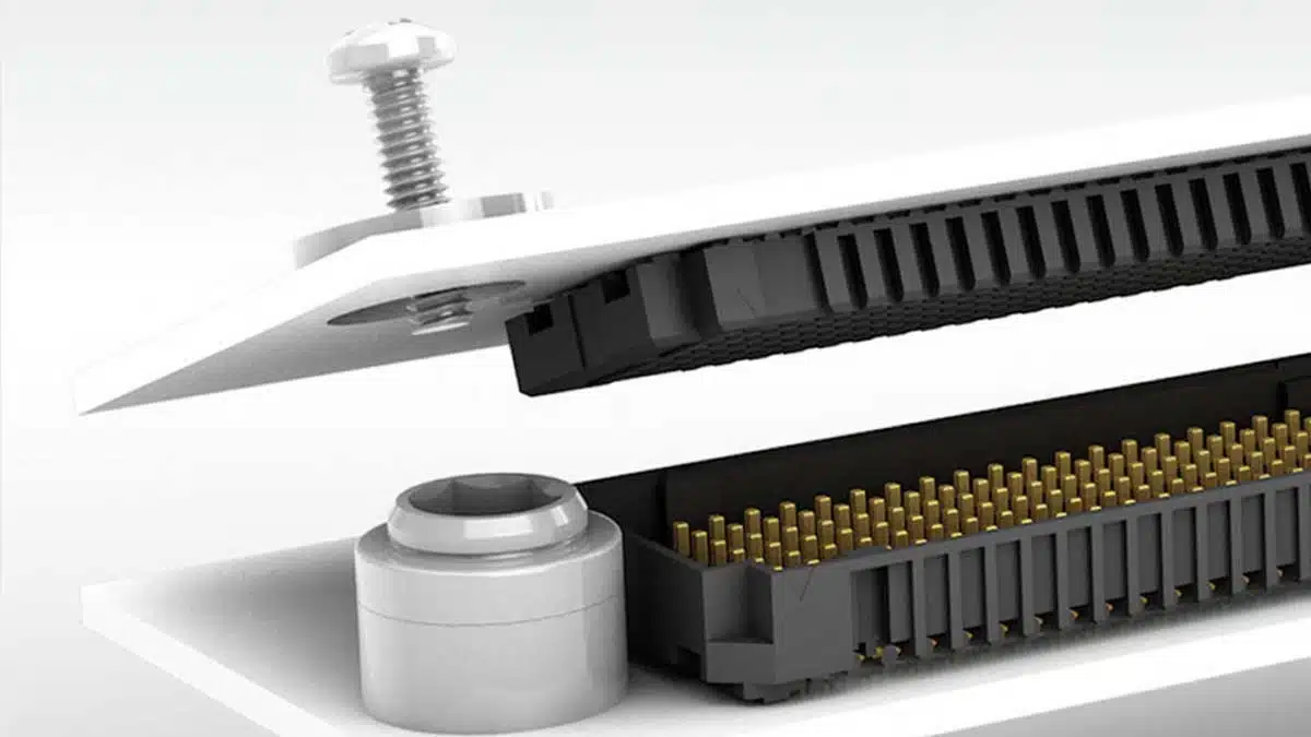
Let’s delve into a single connector mezzanine application. In such an application, the daughtercard is assumed to be free-floating, with alignment features integrated within the connectors. This ensures perfect alignment, making it unaffected by PCB fabrication and assembly process tolerances.

However, in multi-connector applications involving two or more connectors, mechanical tolerances accumulate in various directions and distances. Tolerances from the board house for the motherboard and daughtercard, the equipment, and the final assembly process all contribute to cumulative tolerance stacking, which can impact connector functionality.

To ensure the reliability of the final system, predictive analysis should be conducted early in the design stages.

Considerations and Recommendations

From an interconnect perspective, the best starting point for analyzing tolerance stacking is to confirm the final placement of connectors relative to each other on the same board by establishing a connector center of guidance.

Once a center of guidance is established, you can determine misalignment. Misalignment values influence the acceptance limits for tolerance analysis. Even slight misalignment can significantly increase tolerance stack and final assembly pin registration.

In addition to connectors, other elements must also be considered when evaluating alignment, such as:

  • Solder pad size and location
  • Connector placement onto the solder pad before reflow
  • Connector movement during processing
  • Whether the connector self-levels or self-centers
  • Mating/unmating forces
  • If alignment pins or standoffs are used

It can be recommended using standoffs to negate angular and z-axis misalignment effects. However, for optimal results, place standoffs as close to the connector system as possible to localize stress and reduce unsupported PCB span. It’s also advisable to leave standoffs and similar items loose-fitted until post-connector mating, then tighten them to the final torque specifications.

Alignment pins are excellent for guiding connector placement during hand assembly and polarizing the connector to the PCB. However, they can contribute to tolerance stack. Therefore, it is recommended using a product without alignment pins for machine placement or in multi-connector applications. If alignment pins are necessary for machine placement due to polarization, oversizing the drill hole on the PCB is recommended.

Tolerance analysis methods can be performed using an Arithmetic Worst-Case study or a Root Sum of Squares study, depending on the application requirements. For instance, some applications require analyzing zero failure targets, while others allow for a less conservative approach to reach dimensional goals, potentially resulting in lower costs.

Root Sum of Squares (RSS) study: This statistical approach simulates the expected outcomes for all parts used in a multi-connector application, providing a comprehensive analysis of tolerance stack-up.

Arithmetic Worst-Case (AWC) study: This traditional approach calculates the cumulative measurements of all part tolerances at their limits, resulting in the largest or smallest cumulative measurements.

The role of a connector manufacturer involves ensuring that these recommendations are met to achieve high-quality connectors and minimize the risk of failures.  

All components used in system creation and manufacturing have their own tolerances that must be considered in a tolerance stack-up analysis. The combination of these tolerances creates stacking. Included but not limited to are tolerances from the board house, contract equipment manufacturer, and final assembly process. All of these factors impact connector function, so it is important to follow manufacturers’ general guidance to ensure end system reliability.

Connector manufacturer can only control the tolerances of its own connectors. Samtec aims to clearly define connector tolerances, maximum allowable misalignment, footprint and stencil designs, and processing recommendations. Connector print and footprint information is located at the bottom of each product Series tech spec page (for example, samtec.com?SEAM). 

Related

Source: Samtec

Recent Posts

Connector Industry Performance Accelerates Through Mid-2026

31.8.2026
29

Molex Presents MiniMix Hybrid Power and Signal Connectors for Compact Humanoid Joints

6.8.2026
124

Molex Unveils Automotive Ethernet Connectors for Next‑Gen SDV Architectures

2.7.2026
95

binder Prints Electronics on 3D Components Connector Surface

1.7.2026
60

EMC‑Compliant PCB and Connector Design Guidelines

22.6.2026
231

Hirose Releases Ultra‑low Profile FPC‑to‑board Connector

17.6.2026
113

Molex Expanded AirBorn SInergy Hybrid Connectors with 25 A Power Modules

16.6.2026
95

Hirose Releases 0.5 mm Floating Board-to-Board Connector for EV Powertrain Designs

15.6.2026
65

Hirose Expands Compact High‑Voltage EV connectors

21.5.2026
111

Upcoming Events

Sep 10
11:00 - 12:00 CEST

Equipment models and model strategies for Space Missions

Sep 16
17:00 - 18:00 CEST

Designing a 5 kW, 800 V-to-50 V PSFB Converter for Next-Generation Data Centers

Sep 29
16:00 - 17:00 CEST

Cybersecurity 2026

View Calendar

Popular Posts

  • Buck Converter Design and Calculation

    0 shares
    Share 0 Tweet 0
  • LLC Resonant Converter Design and Calculation

    0 shares
    Share 0 Tweet 0
  • Boost Converter Design and Calculation

    0 shares
    Share 0 Tweet 0
  • Earthing Systems and IEC Classification Explained

    0 shares
    Share 0 Tweet 0
  • MLCC and Ceramic Capacitors

    0 shares
    Share 0 Tweet 0
  • Flyback Converter Design and Calculation

    0 shares
    Share 0 Tweet 0
  • Capacitor Charging and Discharging

    0 shares
    Share 0 Tweet 0
  • Audio Capacitors: Choosing Capacitors for Crossover Circuits

    0 shares
    Share 0 Tweet 0
  • Thermistors Basics, NTC and PTC Thermistors

    0 shares
    Share 0 Tweet 0
  • Resistor Symbols

    0 shares
    Share 0 Tweet 0

Newsletter Subscription


Passive Components Blog

© 2015–2026
All rights reserved

  • Home
  • Privacy Policy
  • EPCI Membership & Advertisement
  • About

No Result
View All Result
  • Home
  • Knowledge Blog
  • Dossiers
  • PCNS

© 2015–2026
All rights reserved