













Passive Components Blog
No Result
View All Result
  • Home
  • NewsFilter
    • All
    • Aerospace & Defence
    • Antenna
    • Applications
    • Automotive
    • Capacitors
    • Circuit Protection Devices
    • electro-mechanical news
    • Filters
    • Fuses
    • Inductors
    • Industrial
    • Integrated Passives
    • inter-connect news
    • Market & Supply Chain
    • Market Insights
    • Medical
    • Modelling and Simulation
    • New Materials & Supply
    • New Technologies
    • Non-linear Passives
    • Oscillators
    • Passive Sensors News
    • Resistors
    • RF & Microwave
    • Telecommunication
    • Weekly Digest

    Mechanical SSC Testing as a Structural Diagnostic Tool for Tantalum Capacitor Anodes

    Stackpole Introduces High‑Voltage Low VCR Chip Resistors

    GDT Gas Discharge Tubes: Surge Protection Fundamentals, Selection, and Design‑in Tips

    YMIN Introduces Vibration Resistant Compact Low ESR Aluminum Capacitors for Home Appliances

    Designing a Custom Core Transformer for 10 kW LLC Data Center Power Stages

    Magnetics Design in High‑Frequency GaN Converters

    ECIA Industry Pulse April 2026: Sentiment Cools but Stays Strong

    Industrial Passive Components Markets and Technologies 2026

    Automotive Passive Components Technology Dossier

    Trending Tags

    • Ripple Current
    • RF
    • Leakage Current
    • Tantalum vs Ceramic
    • Snubber
    • Low ESR
    • Feedthrough
    • Derating
    • Dielectric Constant
    • New Products
    • Market Reports
  • VideoFilter
    • All
    • Antenna videos
    • Capacitor videos
    • Circuit Protection Video
    • Filter videos
    • Fuse videos
    • Inductor videos
    • Inter-Connect Video
    • Non-linear passives videos
    • Oscillator videos
    • Passive sensors videos
    • Resistor videos

    Magnetics Design in High‑Frequency GaN Converters

    Qi2 Wireless Charging: Inductors, Capacitors and EMC Filters

    Two‑capacitor paradox explained for engineers

    Capacitances of Nonlinear MLCCs: What Datasheets Don’t Tell You

    Tapped Inductor Buck Converter Fundamentals

    Planar vs Conventional Transformer: When it Make Sense

    Modeling Fringing Field Losses in Inductors & Transformers

    Why Power Inductors Use a Ferrite Core With an Air Gap

    Transformer-Based Power-Line Harvester Magnetic Design

    Trending Tags

    • Capacitors explained
    • Inductors explained
    • Resistors explained
    • Filters explained
    • Application Video Guidelines
    • EMC
    • New Products
    • Ripple Current
    • Simulation
    • Tantalum vs Ceramic
  • Knowledge Blog
  • DossiersNew
  • Suppliers
    • Who is Who
  • PCNS
    • PCNS 2025
    • PCNS 2023
    • PCNS 2021
    • PCNS 2019
    • PCNS 2017
  • Events
  • Home
  • NewsFilter
    • All
    • Aerospace & Defence
    • Antenna
    • Applications
    • Automotive
    • Capacitors
    • Circuit Protection Devices
    • electro-mechanical news
    • Filters
    • Fuses
    • Inductors
    • Industrial
    • Integrated Passives
    • inter-connect news
    • Market & Supply Chain
    • Market Insights
    • Medical
    • Modelling and Simulation
    • New Materials & Supply
    • New Technologies
    • Non-linear Passives
    • Oscillators
    • Passive Sensors News
    • Resistors
    • RF & Microwave
    • Telecommunication
    • Weekly Digest

    Mechanical SSC Testing as a Structural Diagnostic Tool for Tantalum Capacitor Anodes

    Stackpole Introduces High‑Voltage Low VCR Chip Resistors

    GDT Gas Discharge Tubes: Surge Protection Fundamentals, Selection, and Design‑in Tips

    YMIN Introduces Vibration Resistant Compact Low ESR Aluminum Capacitors for Home Appliances

    Designing a Custom Core Transformer for 10 kW LLC Data Center Power Stages

    Magnetics Design in High‑Frequency GaN Converters

    ECIA Industry Pulse April 2026: Sentiment Cools but Stays Strong

    Industrial Passive Components Markets and Technologies 2026

    Automotive Passive Components Technology Dossier

    Trending Tags

    • Ripple Current
    • RF
    • Leakage Current
    • Tantalum vs Ceramic
    • Snubber
    • Low ESR
    • Feedthrough
    • Derating
    • Dielectric Constant
    • New Products
    • Market Reports
  • VideoFilter
    • All
    • Antenna videos
    • Capacitor videos
    • Circuit Protection Video
    • Filter videos
    • Fuse videos
    • Inductor videos
    • Inter-Connect Video
    • Non-linear passives videos
    • Oscillator videos
    • Passive sensors videos
    • Resistor videos

    Magnetics Design in High‑Frequency GaN Converters

    Qi2 Wireless Charging: Inductors, Capacitors and EMC Filters

    Two‑capacitor paradox explained for engineers

    Capacitances of Nonlinear MLCCs: What Datasheets Don’t Tell You

    Tapped Inductor Buck Converter Fundamentals

    Planar vs Conventional Transformer: When it Make Sense

    Modeling Fringing Field Losses in Inductors & Transformers

    Why Power Inductors Use a Ferrite Core With an Air Gap

    Transformer-Based Power-Line Harvester Magnetic Design

    Trending Tags

    • Capacitors explained
    • Inductors explained
    • Resistors explained
    • Filters explained
    • Application Video Guidelines
    • EMC
    • New Products
    • Ripple Current
    • Simulation
    • Tantalum vs Ceramic
  • Knowledge Blog
  • DossiersNew
  • Suppliers
    • Who is Who
  • PCNS
    • PCNS 2025
    • PCNS 2023
    • PCNS 2021
    • PCNS 2019
    • PCNS 2017
  • Events
No Result
View All Result
Passive Components Blog
No Result
View All Result

Bourns Releases Compact High Current Shielded Power Inductors

2.4.2026
Reading Time: 7 mins read
A A

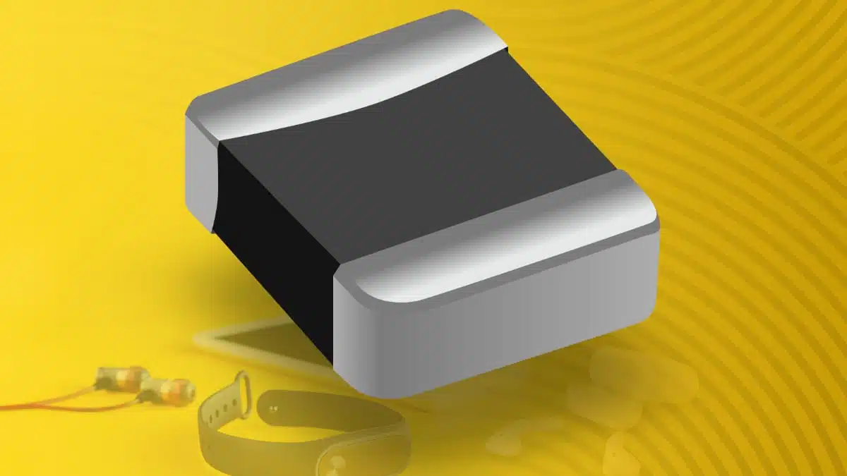
Bourns has introduced the SRP2008DP Series, a family of low‑profile, high current shielded power inductors in a 2.0 × 1.6 × 0.8 mm package for space‑constrained power stages in portable, IoT and compact industrial designs.

The SMD chip inductor series targets design engineers who need to increase power density and manage EMI on crowded PCBs without sacrificing saturation performance.

RelatedPosts

Bourns Expands its Modular Contacts for Power-Dense Systems

Bourns Expanded Semi-Shielded Low Profile Automotive Power Inductor

Bourns Extends PPTC Resettable High‑Power, High‑Voltage Protection Fuses

Key features and benefits

The SRP2008DP power inductor series is built on a metal‑alloy powder core with fully shielded construction. This combination is aimed at high‑frequency DC‑DC converters where low profile, high current capability and controlled magnetic fields are all critical.

Key characteristics include:

  • Shielded construction to contain magnetic flux, reducing radiated emissions and helping with board‑level EMC compliance when components are packed closely together.
  • Metal‑alloy powder core with high resistivity to suppress eddy currents and reduce core losses at the switching frequencies typical of modern converters.
  • High saturation current ratings (Isat up to 5.50 A, depending on value) so inductance is maintained under load and the core is less likely to collapse during transient or peak current events.
  • Heating current (Irms up to 3.50 A) specified so designers can estimate temperature rise and steady‑state current limits more accurately in small enclosures.
  • Very low profile 0.8 mm package height for designs where z‑axis clearance is constrained, such as wearables, compact modules and stacked boards.
  • Wide operating temperature range from −40 °C to +125 °C, supporting typical consumer and many industrial environments.
  • RoHS compliant and halogen‑free construction for designs that must meet current environmental requirements.

For engineers, the key benefit is the ability to use a shielded, high‑current inductor even in layouts that previously would have forced a compromise toward smaller, unshielded components or larger footprints.

Typical applications

Bourns positions the SRP2008DP Series primarily for compact power conversion in modern, miniaturized electronics. The inductor size and current ratings fit a wide range of low‑ to mid‑power DC‑DC converter topologies.

Typical application areas include:

  • DC‑DC converters in portable and handheld devices, such as smartphones, cameras, handheld terminals and medical wearables where every square millimeter of PCB matters.
  • Miniature consumer electronics and wearables that integrate radios, sensors and processing in a single compact PCB and need shielded magnetics to control interference.
  • IoT modules and compact industrial power circuits that require stable power rails in small form‑factor boards, often in harsh or thermally challenging environments.
  • Height‑constrained PCB‑based designs in general, for example stacked boards, low‑profile modules or thin enclosures where component height can be a limiting factor.

In these use cases, the shielded construction helps reduce magnetic coupling into adjacent RF sections, precision analog front‑ends or high‑speed digital traces located near the power stage.

Technical highlights

From a specification perspective, the SRP2008DP Series occupies the low‑μH range suitable for switching converter energy storage while maintaining a very small footprint.

Package and mechanical data

  • Footprint: 2.0 × 1.6 mm outline for minimal board area usage.
  • Height: 0.8 mm maximum profile to match ultra‑slim designs.
  • Package style: SMD, shielded construction based on a metal‑alloy powder core.

The small size simplifies placement near the switching device, which helps minimize loop area and radiated noise while simplifying routing in multi‑rail or multi‑layer designs.

Electrical range (series overview)

According to the manufacturer’s published series data, the SRP2008DP family covers:

  • Inductance values: 0.24 μH to 4.70 μH (nominal range).
  • Heating current Irms: 1.10 A to 3.50 A across the value range.
  • Saturation current Isat: 1.60 A to 5.50 A depending on inductance.

In practice, lower inductance values typically support higher saturation currents, which is suitable for low‑voltage, high‑current converter stages, while higher inductance values serve lower current or higher duty‑cycle applications. Exact ratings, DCR values and tolerance classes should be taken from the current Bourns datasheet for the specific part number selected.

Thermal and environmental characteristics

  • Operating temperature range: −40 °C to +125 °C.
  • RoHS compliant and halogen‑free construction.

A −40 °C to +125 °C rating covers most commercial and many industrial applications, including equipment exposed to moderate ambient temperature rise and self‑heating. Designers should still validate actual component temperature on the target PCB under worst‑case load and airflow conditions.

Design‑in notes for engineers

When selecting a member of the SRP2008DP Series for a specific DC‑DC converter or power rail, a few practical points can improve design robustness.

Inductor selection considerations

  • Check inductance versus operating point: choose an inductance that meets converter ripple and transient response targets at the planned switching frequency, then verify the inductance drop at the expected peak current from the manufacturer’s curves.
  • Use Isat with margin: select a part where the saturation current rating comfortably exceeds the maximum peak current, including startup and fault conditions, not just nominal load.
  • Observe Irms and temperature rise: ensure the heating current rating supports continuous load current with acceptable temperature rise on your specific PCB stackup and enclosure.
  • Review DCR and efficiency: lower DCR improves efficiency and reduces heating, but may trade off against inductance or other parameters; refer to the datasheet tables rather than extrapolating.

Because the SRP2008DP devices are optimized for dense layouts, designers should also consider via placement and copper area beneath and around the component to help spread heat, especially in always‑on rails in thermally constrained housings.

EMI and layout guidance

The shielded construction is designed to reduce stray flux, but layout discipline remains important for low‑noise performance.

  • Keep the loop formed by the switch, diode or synchronous FET, inductor and input capacitor as compact as possible to limit radiated noise.
  • Avoid routing sensitive analog, RF or high‑speed digital lines directly under or adjacent to the inductor; even shielded parts can couple some residual fields at high current.
  • If multiple power rails are implemented with several SRP2008DP inductors in proximity, consider orientation and spacing to further reduce mutual coupling.
  • Use solid ground planes and carefully placed return paths to help control common‑mode emissions in conjunction with the shielded inductor.

For designs that must meet formal EMC standards, pre‑compliance testing with the intended inductor value and layout is recommended before finalizing the PCB.

Source

This article is based on information provided in the official Bourns press release and associated SRP2008DP Series product documentation, with additional independent commentary and design‑in guidance for power electronics engineers.

References

  1. Bourns press release – SRP2008DP Series high current shielded power inductors
  2. Bourns SRP2008DP Series datasheet
  3. Bourns SRP2008DP Series product page

Related

Recent Posts

Stackpole Introduces High‑Voltage Low VCR Chip Resistors

25.5.2026
8

GDT Gas Discharge Tubes: Surge Protection Fundamentals, Selection, and Design‑in Tips

25.5.2026
11

Designing a Custom Core Transformer for 10 kW LLC Data Center Power Stages

22.5.2026
34

Magnetics Design in High‑Frequency GaN Converters

22.5.2026
30

Industrial Passive Components Markets and Technologies 2026

21.5.2026
88

Automotive Passive Components Technology Dossier

21.5.2026
60

Hirose Expands Compact High‑Voltage EV connectors

21.5.2026
18

Qi2 Wireless Charging: Inductors, Capacitors and EMC Filters

21.5.2026
26

Würth Elektronik Presents New Bidirectional Digital Isolators

20.5.2026
36

Upcoming Events

May 27
17:00 - 17:30 CEST

When requirements change: Live Planar redesign under time pressure

Jun 2
16:00 - 17:00 CEST

Calculation, Simulation and Measurement of 800V EMC Filters

Jun 16
16:00 - 17:00 CEST

EMC with EMC – EMC‑compliant design with electromechanical connectors

View Calendar

Popular Posts

  • Buck Converter Design and Calculation

    0 shares
    Share 0 Tweet 0
  • Boost Converter Design and Calculation

    0 shares
    Share 0 Tweet 0
  • Flyback Converter Design and Calculation

    0 shares
    Share 0 Tweet 0
  • LLC Resonant Converter Design and Calculation

    0 shares
    Share 0 Tweet 0
  • MLCC and Ceramic Capacitors

    0 shares
    Share 0 Tweet 0
  • Capacitor Charging and Discharging

    0 shares
    Share 0 Tweet 0
  • What Electronics Engineer Needs to Know About Passive Low Pass Filters

    0 shares
    Share 0 Tweet 0
  • Dual Active Bridge (DAB) Topology

    0 shares
    Share 0 Tweet 0
  • Ripple Current and its Effects on the Performance of Capacitors

    3 shares
    Share 3 Tweet 0
  • Samsung Electro-Mechanics Releases High-Capacitance MLCCs for AI Server Applications

    0 shares
    Share 0 Tweet 0

Newsletter Subscription


Passive Components Blog

© EPCI - Leading Passive Components Educational and Information Site

  • Home
  • Privacy Policy
  • EPCI Membership & Advertisement
  • About

No Result
View All Result
  • Home
  • Knowledge Blog
  • Dossiers
  • PCNS

© EPCI - Leading Passive Components Educational and Information Site

This website uses cookies. By continuing to use this website you are giving consent to cookies being used. Visit our Privacy and Cookie Policy.
Go to mobile version