Passive Components Blog
No Result
View All Result
  • Home
  • NewsFilter
    • All
    • Aerospace & Defence
    • Antenna
    • Applications
    • Automotive
    • Capacitors
    • Circuit Protection Devices
    • electro-mechanical news
    • Filters
    • Fuses
    • Inductors
    • Industrial
    • Integrated Passives
    • inter-connect news
    • Market & Supply Chain
    • Market Insights
    • Medical
    • Modelling and Simulation
    • New Materials & Supply
    • New Technologies
    • Non-linear Passives
    • Oscillators
    • Passive Sensors News
    • Resistors
    • RF & Microwave
    • Telecommunication
    • Weekly Digest

    MLCCs in the Age of AI: Q2 2026 Market Tightness

    AI Hardware Demand for Passive Components Dossier

    June 2026 Interconnect, Passives and Electromechanical Components Market Insights

    KYOCERA AVX Presents Antenna Integrator Studio Tutorial for Antenna Placement and RF Design

    Power Design Simulation Tools for Faster Inductor Selection and Loss Optimization

    Wk 25 Electronics Supply Chain Digest

    Skeleton Supercapacitor Achieves UL‑certified 3,500 A Peak Current for AI Data Centers

    Bourns Planar Transformers for SiC and GaN Gate Driver Isolation

    100 V Hybrid Polymer Capacitor from VINA Enesol Targets 48–72 V Power Platforms

    Trending Tags

    • Ripple Current
    • RF
    • Leakage Current
    • Tantalum vs Ceramic
    • Snubber
    • Low ESR
    • Feedthrough
    • Derating
    • Dielectric Constant
    • New Products
    • Market Reports
  • VideoFilter
    • All
    • Antenna videos
    • Capacitor videos
    • Circuit Protection Video
    • Filter videos
    • Fuse videos
    • Inductor videos
    • Inter-Connect Video
    • Non-linear passives videos
    • Oscillator videos
    • Passive sensors videos
    • Resistor videos

    KYOCERA AVX Presents Antenna Integrator Studio Tutorial for Antenna Placement and RF Design

    Power Design Simulation Tools for Faster Inductor Selection and Loss Optimization

    EMC‑Compliant PCB and Connector Design Guidelines

    Why Isolated DC/DC Power Supplies Fail Late, Würth Elektronik Podcast

    Designing 800 V DC EMC Filters: Calculation, Simulation and Measurement

    Current Sense Transformer Datasheet and Design‑in Guide

    Designing a USB Type‑C Flyback Planar Transformer with Frenetic’s Planar Tool

    Magnetics Design in High‑Frequency GaN Converters

    Qi2 Wireless Charging: Inductors, Capacitors and EMC Filters

    Trending Tags

    • Capacitors explained
    • Inductors explained
    • Resistors explained
    • Filters explained
    • Application Video Guidelines
    • EMC
    • New Products
    • Ripple Current
    • Simulation
    • Tantalum vs Ceramic
  • Knowledge Blog
  • DossiersNew
  • Suppliers
    • Who is Who
  • PCNS
    • PCNS 2025
    • PCNS 2023
    • PCNS 2021
    • PCNS 2019
    • PCNS 2017
  • Events
No Result
View All Result
Passive Components Blog
No Result
View All Result

Hirose Expands Compact High‑Voltage EV connectors

21.5.2026
Reading Time: 8 mins read
A A

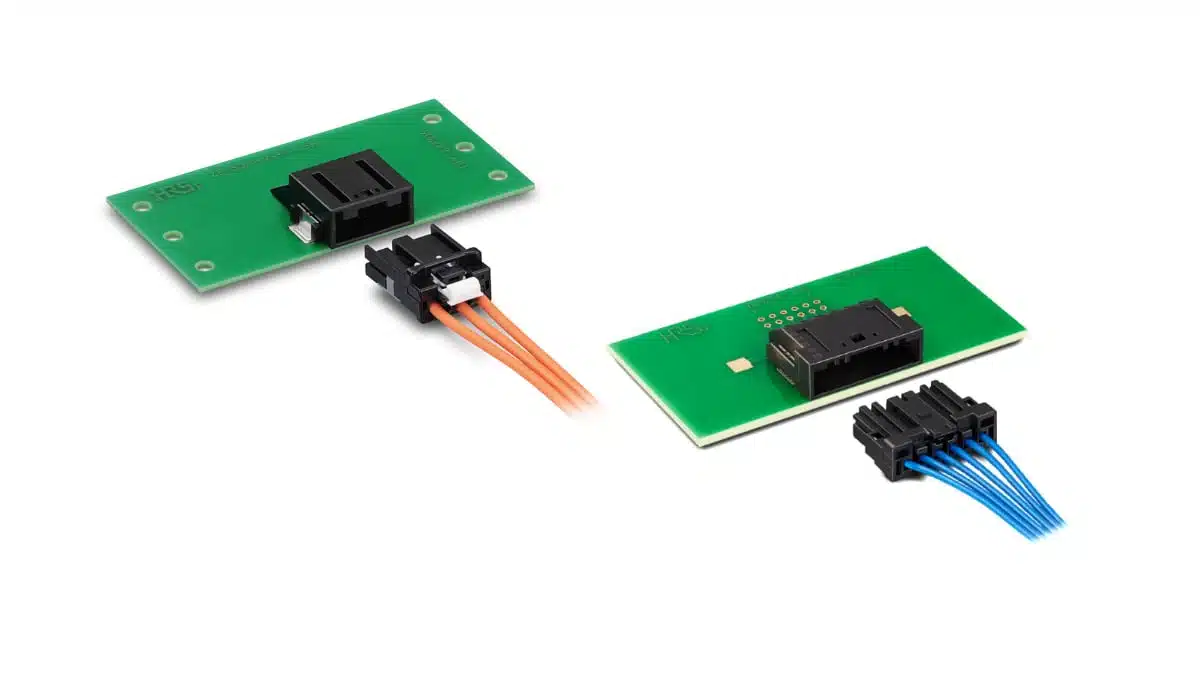
Hirose’s ZE150HV and ZG05HV connector families are compact wire‑to‑board solutions for high‑voltage circuits in electric and hybrid vehicles as well as industrial battery systems.

They are designed for up to 1,000 V operation with enhanced creepage/clearance, robust vibration performance, and options tailored to both high‑current and signal/low‑power lines. This makes them attractive for engineers who need to route high‑voltage wiring safely into PCBs in constrained EV/HEV powertrain and stationary storage designs.

RelatedPosts

Hirose Releases Ultra‑low Profile FPC‑to‑board Connector

Hirose Releases 0.5 mm Floating Board-to-Board Connector for EV Powertrain Designs

Hirose Introduced BGA connector for PCIe Gen6 for AI and Edge Computing

Key features and benefits

  • High‑voltage rating for modern EV architectures
    Both ZE150HV and ZG05HV are rated for operation up to 1,000 V AC/DC with a 3,000 V AC withstand level for one minute, according to IEC 60664 (pollution degree 2, up to 6,000 m altitude).
  • Wide automotive operating temperature range
    The connectors are specified from −40 °C to +125 °C, covering typical automotive under‑hood and battery enclosure environments.
  • Compact footprints with optimized creepage and clearance
    A proprietary ribbed housing design increases the effective surface path between contacts, allowing high‑voltage ratings in comparatively small connector sizes.
  • Vibration‑robust contact system
    Dual‑spring, three‑point contacts are used to increase contact force and maintain continuity under vehicle vibration and dynamic loading.
  • Connector Position Assurance (CPA) option for safety
    The ZE150HV version integrates a CPA mechanism that helps prevent incomplete mating and reduces the risk of arcing or intermittent connection at high voltage.
  • Wire gauges adapted to power vs. signal needs
    ZE150HV supports thicker automotive wires for higher current, while ZG05HV targets smaller gauges suitable for low‑current or sensing lines.
  • Surface‑mount and THR mounting options
    ZE150HV is offered as an SMT connector, whereas ZG05HV uses through‑hole reflow (THR), giving layout flexibility for designers balancing assembly flow and mechanical robustness.

Typical applications

The ZE150HV and ZG05HV series target high‑voltage subsystems where wiring harnesses must interface reliably with power electronics and battery modules.

  • EV and HEV traction inverters and converters in the powertrain
  • On‑board chargers and DC/DC converters for high‑voltage battery systems
  • Battery packs and storage modules in electric vehicles and industrial systems
  • Stationary energy storage such as industrial storage batteries and smart‑grid battery modules
  • Other high‑voltage automotive subsystems where compact, vibration‑resistant wire‑to‑board connections are needed

In many of these systems, the connectors provide a defined, removable interface between a cable harness and a high‑voltage PCB, simplifying assembly, serviceability, and modular system design.

Technical highlights

For quick comparison of the two series, the table below summarizes the key electrical and mechanical parameters.

ZE150HV vs. ZG05HV series overview

ParameterZE150HV seriesZG05HV series
Nominal contact size / pitch1.5 size, 4.5 mm pitch0.5 size, 3.3 mm pitch
Rated current (all pins powered)10 A per pin1 A per pin
Rated voltage1,000 V AC/DC (per IEC 60664 conditions)1,000 V AC/DC (per IEC 60664 conditions)
Withstand voltage3,000 V AC for 1 minute3,000 V AC for 1 minute
Insulation resistanceMinimum 100 MΩ at 1,000 V DCMinimum 100 MΩ at 1,000 V DC
Operating temperature−40 °C to +125 °C−40 °C to +125 °C
Mating durability30 mating cycles30 mating cycles
PCB mountingSurface‑mount technology (SMT)Through‑hole reflow (THR)
Applicable wire size16–18 AWG (0.75–1.25 mm²)22 and 24 AWG (0.22–0.35 mm²)

The combination of 1,000 V rating and 3,000 V withstand voltage addresses the insulation requirements of many 400 V and 800 V class EV platforms, under the specified pollution degree and altitude. In practice, designers still need to verify that the creepage and clearance distances on the associated PCB and in the surrounding system meet the overall insulation coordination requirements for their target standard.

High‑voltage housing design

Hirose optimizes creepage and clearance by adding ribs and shaping the plastic housing to increase the effective path between adjacent contacts and between contacts and external conductive parts. This approach is particularly relevant at 1,000 V, where required creepage distances can otherwise force large connector footprints. For engineers, this means the ZE150HV and ZG05HV can be placed in tighter spaces while still meeting insulation targets when used according to the datasheet and applicable standards.

Vibration‑resistant contact geometry

The dual‑spring, three‑point contact system provides both higher contact normal force and multiple contact points per terminal. In vehicle applications subject to continuous vibration and shock, this helps maintain low and stable contact resistance over life. It also reduces the risk of momentary interruptions that could disturb high‑voltage control or sensing circuits, which is especially important in safety‑related power electronics.

CPA mechanism on ZE150HV

The Connector Position Assurance mechanism used on the ZE150HV series is designed to detect and prevent incomplete mating. Once fully engaged, the CPA locks or verifies the position so that the connector cannot remain in a “half‑mated” state. In high‑voltage systems this is critical: partial insertion can lead to arcing, heating, or intermittent faults under load. The ZG05HV focuses on compactness for smaller conductors and does not include the CPA feature, so designers should evaluate where CPA is mandatory in the system and select the series appropriately.

Design‑in notes for engineers

Series selection and partitioning

  • Use ZE150HV where higher current is needed; the 10 A per pin capability and 16–18 AWG support suit power lines between battery modules, inverters, and DC/DC converters.
  • Use ZG05HV where only small currents or signals are present; its 1 A per pin rating and 22–24 AWG support make it suitable for sensing, control, and monitoring lines within the same high‑voltage environment.
  • Consider mixed usage in a system: ZE150HV for main power paths, ZG05HV for auxiliary or sensing harnesses, keeping voltage class consistent but optimizing size and copper usage.

Layout and insulation coordination

  • Respect the manufacturer’s creepage/clearance recommendations and IEC 60664 assumptions (pollution degree 2, up to 6,000 m altitude) when defining the PCB land pattern and keep‑out areas.
  • Ensure that PCB traces, copper pours, and mechanical structures around the connector do not compromise the effective creepage path provided by the ribbed housing design.
  • For SMT ZE150HV, verify solder joint fillet and mechanical support in vibration‑heavy locations; additional mechanical fixing or potting may be beneficial in some designs.

Vibration and mechanical robustness

  • The dual‑spring, three‑point contacts help, but system‑level vibration testing is still necessary for critical automotive use cases; consider where to place connectors to minimize exposure to extreme mechanical stress.
  • Confirm that harness routing supports the connector and avoids heavy cable loads acting as a lever on the PCB, particularly for SMT versions on thinner boards.

Thermal considerations

  • Current ratings are specified under defined conditions; for continuous high‑current operation in hot environments close to +125 °C, evaluate temperature rise in your specific layout and cooling conditions.
  • Combine the connector’s operating temperature range with the expected ambient and self‑heating of adjacent power components (IGBTs, SiC MOSFETs, inductors, etc.) to ensure sufficient margin.

Assembly and quality

  • In designs using ZE150HV, make sure manufacturing and service procedures explicitly include the CPA operation and verification, so incomplete mating is avoided on the line and in the field.
  • For ZG05HV THR mounting, coordinate reflow profiles so that connector plastics and wire terminations remain within their specified temperature limits while achieving reliable solder joints.
  • Plan for the 30‑cycle mating durability by avoiding unnecessary disconnects during testing and service; for frequently reconnected interfaces, consider whether additional protection or an alternative interconnect strategy is needed.

Source

This article is based on information from Hirose Electric’s official product information for the ZE150HV and ZG05HV high‑voltage automotive connector series and related manufacturer documentation, interpreted and summarized for design engineers and component purchasers.

References

  1. Hirose Electric – ZE150HV/ZG05HV Series High-Voltage Automotive Connector
  2. Hirose Electric – ZE150HV Series product page
  3. Hirose Electric – ZG05HV Series product page

Related

Recent Posts

MLCCs in the Age of AI: Q2 2026 Market Tightness

30.6.2026
10

Skeleton Supercapacitor Achieves UL‑certified 3,500 A Peak Current for AI Data Centers

26.6.2026
46

Bourns Planar Transformers for SiC and GaN Gate Driver Isolation

26.6.2026
33

100 V Hybrid Polymer Capacitor from VINA Enesol Targets 48–72 V Power Platforms

26.6.2026
100

Panasonic Releases Relays for IEC 62955 Compliant Single‑Phase EV Wallboxes

25.6.2026
23

Bourns Introduced High-Current Coupled Inductor for 48 V Hybrid and IBC Converters

24.6.2026
35

Würth Elektronik Expands Nanocrystalline Cable Cores for Broadband EMI Suppression

23.6.2026
27

Bourns Introduced Automotive TVS Diodes for Compact ESD Protection

23.6.2026
37

EMC‑Compliant PCB and Connector Design Guidelines

22.6.2026
53

Upcoming Events

Jun 30
17:00 - 18:00 CEST

PSMA Capacitor Committee Webinar: High Voltage Pulse Capacitors

Jul 2
17:30 - 18:30 CEST

Can Claude design a production-ready Custom Magnetic Component?

Jul 14
16:00 - 17:00 CEST

EMC Design Essentials: Mastering Varistors and Common Mode Chokes

View Calendar

Popular Posts

  • Boost Converter Design and Calculation

    0 shares
    Share 0 Tweet 0
  • Buck Converter Design and Calculation

    0 shares
    Share 0 Tweet 0
  • Flyback Converter Design and Calculation

    0 shares
    Share 0 Tweet 0
  • LLC Resonant Converter Design and Calculation

    0 shares
    Share 0 Tweet 0
  • MLCC and Ceramic Capacitors

    0 shares
    Share 0 Tweet 0
  • Nvidia Vera Rubin: Why One AI Rack Needs So Many More MLCC Capacitors

    0 shares
    Share 0 Tweet 0
  • Earthing Systems and IEC Classification Explained

    0 shares
    Share 0 Tweet 0
  • Dual Active Bridge (DAB) Topology

    0 shares
    Share 0 Tweet 0
  • SEPIC Converter Design and Calculation

    0 shares
    Share 0 Tweet 0
  • MLCC Case Sizes Standards Explained

    0 shares
    Share 0 Tweet 0

Newsletter Subscription


Passive Components Blog

© EPCI - Leading Passive Components Educational and Information Site

  • Home
  • Privacy Policy
  • EPCI Membership & Advertisement
  • About

No Result
View All Result
  • Home
  • Knowledge Blog
  • Dossiers
  • PCNS

© EPCI - Leading Passive Components Educational and Information Site

This website uses cookies. By continuing to use this website you are giving consent to cookies being used. Visit our Privacy and Cookie Policy.
Go to mobile version