Passive Components Blog
No Result
View All Result
  • Home
  • NewsFilter
    • All
    • Aerospace & Defence
    • Antenna
    • Applications
    • Automotive
    • Capacitors
    • Circuit Protection Devices
    • electro-mechanical news
    • Filters
    • Fuses
    • Inductors
    • Industrial
    • Integrated Passives
    • inter-connect news
    • Market & Supply Chain
    • Market Insights
    • Medical
    • Modelling and Simulation
    • New Materials & Supply
    • New Technologies
    • Non-linear Passives
    • Oscillators
    • Passive Sensors News
    • Resistors
    • RF & Microwave
    • Telecommunication
    • Weekly Digest

    Binder Hybrid Connector Simplifies One Cable Automation

    Tapped Inductor Buck Converter Fundamentals

    TAIYO YUDEN Releases Mini Metal Power Inductors

    Molecular Memristor Shows Record 145 kH Emergent Inductance

    Planar vs Conventional Transformer: When it Make Sense

    Researchers Propose Next‑Gen Compact Memory Using Ultra-thin Ferroelectric Capacitors

    Nichicon ADN Automotive Hybrid Aluminum Capacitors Now Available in EMEA

    Wk 19 Electronics Supply Chain Digest

    Electrocaloric Multilayer Capacitors: Towards Quiet, Solid‑State Cooling Around Room Temperature

    Trending Tags

    • Ripple Current
    • RF
    • Leakage Current
    • Tantalum vs Ceramic
    • Snubber
    • Low ESR
    • Feedthrough
    • Derating
    • Dielectric Constant
    • New Products
    • Market Reports
  • VideoFilter
    • All
    • Antenna videos
    • Capacitor videos
    • Circuit Protection Video
    • Filter videos
    • Fuse videos
    • Inductor videos
    • Inter-Connect Video
    • Non-linear passives videos
    • Oscillator videos
    • Passive sensors videos
    • Resistor videos

    Tapped Inductor Buck Converter Fundamentals

    Planar vs Conventional Transformer: When it Make Sense

    Modeling Fringing Field Losses in Inductors & Transformers

    Why Power Inductors Use a Ferrite Core With an Air Gap

    Transformer-Based Power-Line Harvester Magnetic Design

    Thermal Modeling of Magnetics

    Standard vs Planar LLC transformers Comparison for Battery Chargers

    How Modern Tools Model Magnetic Components for Power Electronics

    Advanced Loss Modeling for Planar Magnetics in the Frenetic Planar Tool

    Trending Tags

    • Capacitors explained
    • Inductors explained
    • Resistors explained
    • Filters explained
    • Application Video Guidelines
    • EMC
    • New Products
    • Ripple Current
    • Simulation
    • Tantalum vs Ceramic
  • Knowledge Blog
  • DossiersNew
  • Suppliers
    • Who is Who
  • PCNS
    • PCNS 2025
    • PCNS 2023
    • PCNS 2021
    • PCNS 2019
    • PCNS 2017
  • Events
No Result
View All Result
Passive Components Blog
No Result
View All Result

Coilcraft Releases TLVR Inductors for High Density VRMs and PoL Converters

19.3.2026
Reading Time: 6 mins read
A A

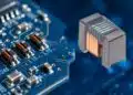
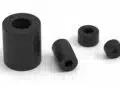
Coilcraft has introduced a new family of Trans‑Inductor Voltage Regulator (TLVR) power inductors optimized for modern multi‑phase voltage regulator modules (VRMs) and point‑of‑load (PoL) converters.

These power inductor devices are aimed at high‑current rails in next‑generation CPUs, GPUs, ASICs and SoCs, where very fast transient response and high power density are critical.

RelatedPosts

Coilcraft Unveils Molded Power Inductors for High‑Current VRMs

Coilcraft Releases Automotive Common Mode Chokes

Coilcraft Introduces Ultra-Low Loss Shielded Power Inductors

Key features and benefits

The TLVR inductors are designed specifically for multi‑phase VRM and PoL topologies where several phases operate in parallel to supply low‑voltage, high‑current loads. In such architectures, inductor performance directly impacts transient response, efficiency and board area.

Key characteristics highlighted by Coilcraft include:

  • Designed for VRMs and PoL converters using the latest multi‑phase topologies
  • Low DC resistance (DCR) to reduce conduction losses and improve efficiency, especially at high currents
  • Tight magnetic coupling, which supports TLVR operation and helps improve transient response in multi‑phase designs
  • Excellent thermal performance, important for maintaining inductance and reliability at elevated temperatures and high currents
  • Compact footprints enabling high power density around the processor or controller
  • Specific SLV series options with high saturation currents up to 120 A and 152 A, supporting demanding core and memory rails

For power designers, low DCR and high saturation current mean that the inductor can carry the required ripple and transient currents with manageable temperature rise and without significant loss of inductance. Tight coupling within the TLVR structure is particularly useful in high‑speed digital systems where rapid load steps are common.

Typical applications

The TLVR power inductors are intended for power stages serving advanced digital ICs where supply stability and transient performance are critical. Typical target applications include:

  • Core and auxiliary rails for next‑generation CPUs and server‑class processors
  • High‑current power rails for GPUs used in AI accelerators, graphics, and data center workloads
  • Power delivery for custom ASICs and SoCs in networking, storage, and communication equipment
  • Server and data center VRMs, especially in space‑constrained motherboard and accelerator card designs
  • Other high‑current point‑of‑load converters in computing and industrial power systems

In these systems, fast load transients—such as a CPU switching between low‑power and turbo modes—require inductors that support rapid current slew while keeping voltage deviations within tight limits. The combination of low DCR, tight coupling and high saturation current directly addresses this requirement.

Technical highlights

Within the TLVR offering, Coilcraft highlights two shielded inductor series optimized for different current and size points.

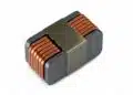
The SLV9080 series is a compact TLVR inductor option with automotive‑qualified variants:

  • High saturation current up to 120 A
  • Seven inductance values from 50 nH to 200 nH
  • Compact footprint of 9.15 × 6.4 mm, supporting dense VRM layouts
  • AEC‑Q200 qualified, making it suitable for automotive power applications where extended temperature range and reliability testing are required

Inductance values in the 50–200 nH range are typical for modern multi‑phase VRMs where high switching frequencies and large phase counts are used to deliver hundreds of amperes with low output ripple. AEC‑Q200 qualification indicates that the series has been tested against a standardized set of stress tests for passive components in automotive environments.

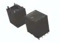
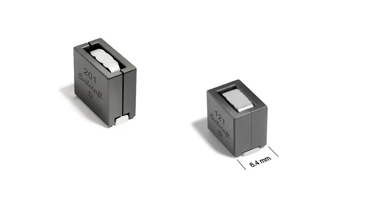
The SLV1211 series addresses even higher current rails while maintaining a compact form factor:

  • High saturation current up to 152 A
  • Six inductance values from 70 nH to 200 nH
  • Compact 12 × 6 mm footprint

By providing higher saturation current in a slightly larger footprint, this series is positioned for the most demanding rails in processors, GPUs or custom accelerators. Designers can choose inductance values to balance transient response, ripple current and efficiency according to the converter’s switching frequency and control strategy.

Design‑in notes for engineers

When designing multi‑phase VRMs or PoL converters with TLVR inductors, several practical considerations can help ensure robust performance:

  • Match inductance to control strategy: For a given switching frequency and number of phases, lower inductance values from the 50–200 nH range will typically improve transient response but increase ripple current, while higher inductance values reduce ripple at the cost of slower current slew. Selection should be made based on the allowable ripple and transient undershoot/overshoot.
  • Verify current ratings against worst‑case conditions: Use both saturation and thermal ratings from the datasheet to ensure the chosen inductor can handle peak transient currents and steady‑state RMS currents, including margin for elevated ambient temperatures and restricted airflow.
  • Layout around hot spots: The compact footprints of 9.15 × 6.4 mm and 12 × 6 mm allow careful placement close to the IC power pins, minimizing parasitic inductance in the current paths. Designers should keep loop areas small and use wide copper pours to reduce losses and improve thermal spreading.
  • Consider automotive requirements early: If the end application targets automotive or transportation markets, selecting AEC‑Q200 qualified devices such as the SLV9080 series from the outset can avoid later redesigns. Also verify operating temperature range and any specific OEM or Tier‑1 qualification needs.
  • Thermal management: Excellent thermal performance is highlighted for the TLVR family, but real‑world behavior still depends on PCB copper, airflow and neighboring hot components. Use manufacturer‑provided thermal derating curves along with system‑level thermal simulations or measurements to validate margin.
  • EMI and shielding: Shielded TLVR inductors can help reduce radiated emissions compared to open‑frame designs. In dense VRM areas, consider overall EMI strategy, including filter placement, ground referencing, and where necessary additional input and output filtering to meet regulatory limits.

By combining low DCR, tight coupling and high saturation currents in compact shielded packages, the SLV TLVR series offers a practical option for engineers looking to optimize power density and transient performance in current‑generation and upcoming platforms.

Source

This article is based on information provided by Coilcraft in their product announcement and associated online TLVR inductor family pages, complemented with general power electronics design considerations.

References

  1. Coilcraft press release – TLVR Power Inductors
  2. Coilcraft TLVR inductors – family overview
  3. Coilcraft SLV9080 series TLVR inductors
  4. Coilcraft SLV1211 series TLVR inductors

Related

Recent Posts

Binder Hybrid Connector Simplifies One Cable Automation

13.5.2026
3

Tapped Inductor Buck Converter Fundamentals

13.5.2026
9

TAIYO YUDEN Releases Mini Metal Power Inductors

13.5.2026
6

Planar vs Conventional Transformer: When it Make Sense

11.5.2026
35

Nichicon ADN Automotive Hybrid Aluminum Capacitors Now Available in EMEA

11.5.2026
22

High-Crystallinity Nanocrystalline Composites for MHz Chip Inductors

7.5.2026
63

Stackpole Expanded its AlN Thick Film Chip Resistors

6.5.2026
22

Würth Elektronik Introduces Compact Flat-wire SMT Power Inductors for Automotive

5.5.2026
49

KYOCERA AVX Extends MLV Varistors for 48V Automotive Protection

5.5.2026
26

Upcoming Events

May 13
17:00 - 17:30 CEST

Winding Loss Modeling for Toroidal Magnetics – Including Gapped Cores

May 19
16:00 - 17:00 CEST

Designing Qi2 Wireless Power Systems: Practical Development and EMC Optimization

Jun 2
16:00 - 17:00 CEST

Calculation, Simulation and Measurement of 800V EMC Filters

View Calendar

Popular Posts

  • Buck Converter Design and Calculation

    0 shares
    Share 0 Tweet 0
  • Boost Converter Design and Calculation

    0 shares
    Share 0 Tweet 0
  • Flyback Converter Design and Calculation

    0 shares
    Share 0 Tweet 0
  • LLC Resonant Converter Design and Calculation

    0 shares
    Share 0 Tweet 0
  • MLCC and Ceramic Capacitors

    0 shares
    Share 0 Tweet 0
  • Dual Active Bridge (DAB) Topology

    0 shares
    Share 0 Tweet 0
  • What Electronics Engineer Needs to Know About Passive Low Pass Filters

    0 shares
    Share 0 Tweet 0
  • Capacitor Charging and Discharging

    0 shares
    Share 0 Tweet 0
  • Ripple Current and its Effects on the Performance of Capacitors

    3 shares
    Share 3 Tweet 0
  • MLCC Case Sizes Standards Explained

    0 shares
    Share 0 Tweet 0

Newsletter Subscription


Passive Components Blog

© EPCI - Leading Passive Components Educational and Information Site

  • Home
  • Privacy Policy
  • EPCI Membership & Advertisement
  • About

No Result
View All Result
  • Home
  • Knowledge Blog
  • PCNS

© EPCI - Leading Passive Components Educational and Information Site

This website uses cookies. By continuing to use this website you are giving consent to cookies being used. Visit our Privacy and Cookie Policy.
Go to mobile version