


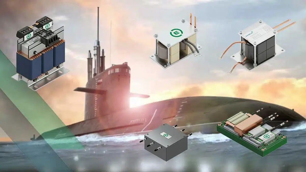
Exxelia has highlighted a set of custom transformers and inductors engineered specifically for naval power conversion, measurement and degaussing systems in harsh maritime environments.
These build‑to‑spec magnetics target applications where shock, vibration, saline humidity and high ambient temperatures make standard catalog parts risky or impractical. For design engineers and purchasers, they illustrate what can realistically be achieved when naval magnetics are co‑developed around system‑level electrical, thermal and mechanical requirements.
Key features and benefits
Exxelia’s naval magnetics portfolio presented in this release is not a fixed product line but a series of executed custom designs that serve as reference points for new projects. The focus is on combining high power density, long‑term reliability and robust insulation in compact mechanical envelopes suitable for constrained shipboard spaces.
Key characteristics across the examples include:
- Build‑to‑spec engineering of transformers and inductors, rather than off‑the‑shelf catalog parts, enabling optimization of geometry, winding style and terminations for each naval platform.
- Designs qualified for harsh environments with shock, vibration and saline humidity, targeting naval and defense‑grade reliability over multi‑decade service life according to the manufacturer.
- Support for multiple cooling strategies (natural convection, forced air, conduction via cold plate, and indirect water cooling) to maintain hot‑spot temperatures within safe limits at high continuous load.
- Emphasis on magnetic material selection (including powder and nanocrystalline cores) to handle strong DC and AC superimposed currents without saturation in high‑current inductors.
- Integration of electrical functions (for example combining transformer and inductor roles in a single self‑transformer assembly) to save space and reduce interconnect complexity in crowded propulsion or reactor bays.
For naval programs seeking size, weight and power (SWaP) improvements, these types of magnetics can help avoid over‑designing enclosures or cooling systems while still meeting conservative derating policies.
Typical applications
The examples in the press release cover several key areas of naval electrical architectures, from low‑frequency measurement to high‑power conversion and degaussing. Each magnetic solution is tailored to a specific subsystem, but the underlying design approaches are transferable to similar platforms.
Typical targeted applications include:
- Measurement chains and monitoring systems using low‑frequency isolated transformers to provide galvanic isolation and accurate sensing of onboard networks around 60 Hz.
- High‑power DC/DC or AC/DC converters in radars, sonars and general naval power supplies using high‑frequency transformers in the tens of kilowatts range to reduce volume and weight.
- Naval nuclear reactor and propulsion systems using self‑transformer assemblies that combine energy transformation and filtering in a single mechanical structure.
- Degaussing systems for magnetic signature reduction using high‑frequency self‑inductors capable of handling high DC currents with AC ripple, while avoiding core saturation.
- Main power distribution on surface ships and submarines relying on high‑power inductors up to around 300 kVA with water‑cooled construction to achieve high power density in hot engine rooms.
For engineers working outside the naval domain, similar build‑to‑spec magnetic concepts can often be transferred to rail traction, offshore energy or other mission‑critical platforms with comparable environmental constraints.
Technical highlights
The press release showcases five flagship products with indicative electrical and mechanical parameters. These are example realizations rather than rigid catalog limits, and final ratings are to be confirmed against the manufacturer datasheets and project‑specific specifications.
Low Frequency Isolated Transformer for measuring chains
This transformer is intended for precision measurement of onboard networks at low frequency. It offers:
- Typical apparent power around 30 VA at 60 Hz, with a focus on linearity and signal integrity rather than bulk power transfer.
- A compact housing with indicative dimensions of approximately 120 × 100 × 135 mm, allowing integration into measurement cabinets or switchboards where space is limited.
- High galvanic isolation between primary and secondary to protect downstream electronics and maintain safety barriers in the presence of high line voltages.
In practice, such a transformer is suited for current or voltage sensing where accurate reproduction of waveforms is essential for protective relays, condition monitoring or power quality analysis.
High Frequency Transformer for high‑power naval solutions
To support SWaP‑driven power electronics, Exxelia presents a high‑frequency transformer designed for high‑power conversion:
- Typical power levels from around 10 kW up to and beyond 100 kW, operating roughly in the 20 kHz to 100 kHz frequency band according to the example values.
- Use of advanced winding technologies such as proprietary Litz wires, foil or flat conductors to reduce AC losses at high frequency and improve thermal performance.
- Compatibility with forced air or liquid cooling, depending on the converter architecture and available thermal interfaces.
Running transformers at higher frequency enables significant reductions in core size and magnetic material volume, but requires careful control of leakage inductance, parasitics and insulation design to maintain efficiency and withstand transients.
20 kW / 35 µH Self‑Transformer Assembly for reactors
The self‑transformer assembly example is aimed at naval nuclear reactor or propulsion systems where both transformation and inductance functions are needed in a single assembly:
- Indicated electrical characteristics around 20 kW and 35 µH, operating at medium to high frequency depending on the system design.
- Mechanical construction optimized for extreme mechanical shock and vibration, with military‑grade qualification targets highlighted in the manufacturer’s communication.
- Long‑term reliability expectations over decades of operation, with substantial safety margins and materials selected for radiation and environmental resistance according to the application.
Combining transformer and inductor roles in one block can simplify mechanical integration, reduce cabling and minimize field coupling issues, but it also demands very careful electromagnetic and thermal modelling early in the design phase.
High Frequency Self‑Inductor for degaussing systems
For degaussing systems, a dedicated high‑frequency self‑inductor is shown as an example of a component designed for strong DC plus AC currents:
- Capability to carry high DC currents with superimposed AC ripple, intended to generate controlled magnetic fields for ship signature reduction.
- Use of core materials such as powder or nanocrystalline alloys, selected to delay saturation under combined DC and AC excitation and to manage losses at the operating frequency.
- Mechanical robustness specifically oriented toward naval environments, including resistance to vibrations from rotating machinery and general shipboard shock.
In practical terms, this type of inductor functions as the main energy storage and filtering element in degaussing converters, where saturation or excessive heating would compromise the ability to maintain the desired magnetic field profile.
High Power Naval Inductor (300 kVA)
For main distribution and smoothing functions, Exxelia presents a high‑power inductor capable of handling substantial apparent power:
- Example rating up to approximately 300 kVA over a broad frequency domain from around 50 Hz up to about 500 kHz, depending on the specific design variant.
- Implementation of indirect water cooling via integrated heat exchangers, providing higher power density than air‑cooled inductors while maintaining electrical insulation and mechanical integrity.
- Design validated for hot ambient conditions up to roughly 75 °C and pressure resistance tested to about 12 bar, aligning with installation in engine rooms or confined compartments with limited air circulation.
For system integrators, such liquid‑cooled inductors can enable more compact switchboards or power distribution modules, but they require coordinated design of cooling circuits, piping and maintenance procedures.
Example comparison table
The manufacturer provides a high‑level comparison of the example designs, summarizing their function and typical characteristics:
| Product | Primary function | Typical values (example) | Frequency range (example) | Cooling technology | Typical application |
|---|---|---|---|---|---|
| LF Isolated Transformer | Galvanic isolation & measurement | ~30 VA signal level | Around 60 Hz | Natural convection | Measurement chains, network monitoring |
| HF Power Transformer | Power conversion (DC/DC or AC/DC) | ~10 kW to 100 kW+ | ~20 kHz to 100 kHz+ | Forced air or liquid cooling | Power supplies, radars, sonars |
| Self‑Transformer Assembly | Combined filtering & transformation | ~20 kW / 35 µH | Medium / high frequency | Conduction / cold plate | Reactors, propulsion |
| HF Self‑Inductor | High‑current filtering | Hundreds of amps (example) | High‑frequency operation | Air or liquid cooling | Degaussing systems, magnetic protection |
| High Power Inductor | Smoothing & distribution | Up to ~300 kVA | ~50 Hz to 500 kHz | Indirect water cooling | Main power distribution, submarines |
Values above are indicative and should be validated against the relevant datasheet and project specification before use in a final design.
Availability and customization
The press release makes clear that these naval magnetics are custom engineered components delivered against project‑specific requirements, not fixed part numbers that can be ordered directly from a standard catalog. The highlighted transformers and inductors should therefore be treated as design templates illustrating performance envelopes and integration approaches.
For purchasing teams and system architects, the typical engagement model is:
- Definition of electrical specification: nominal and peak power, voltage and current ranges, frequency, insulation and test requirements, EMC constraints.
- Mechanical and environmental definition: available envelope, mounting interface, cooling strategy (air, conduction, liquid), shock/vibration test profiles and allowable mass.
- Co‑engineering phase: Exxelia’s R&D teams use finite element analysis for thermal and electromagnetic modelling, followed by prototyping, qualification and final release to production.
Lead times, unit costs and minimum order quantities will depend heavily on the level of customization, qualification effort and documentation required for the naval program.
Design‑in notes for engineers
When evaluating similar build‑to‑spec transformers and inductors for naval platforms, several practical points can help streamline the design‑in process and reduce risk. These apply both to the Exxelia examples and to custom naval magnetics in general.
Key technical considerations include:
- Define operating profiles precisely: duty cycles, overload events, fault conditions and expected lifetime must be specified so that core losses, copper losses and hot‑spot temperatures can be accurately modelled.
- Decide early on the cooling concept: natural convection, forced air, conduction to a cold plate or water cooling all impose different mechanical constraints and influence insulation systems and materials selection.
- Clarify isolation and creepage requirements: required insulation levels, test voltages, pollution degree and overvoltage category drive bobbin design, clearances and impregnation or encapsulation choices.
- Address EMC from the start: for high‑frequency transformers and inductors, leakage inductance, parasitic capacitances and winding layout significantly impact conducted and radiated emissions, and may require integrated shields or specific interleaving patterns.
- Consider magnetic signature implications: in naval applications, unintended stray fields from large magnetics can couple into nearby cabling or sensitive equipment, so the mechanical location, orientation and shielding strategy should be part of the early layout.
From a documentation standpoint, requesting manufacturer models (lumped‑element, behavioral or FEA‑derived) can support more accurate system‑level simulations, especially when operating in wide frequency ranges or with complex multiphase topologies.
Source
The information in this article is based on an official Exxelia press release describing several custom naval magnetic solutions, including example specifications and application contexts. Exact electrical and mechanical values for any given project should always be confirmed against the corresponding manufacturer datasheet and formal specification documents.
References
- Exxelia – Naval Magnetic Solutions: Mission‑Critical Reliability & Build‑to‑Spec Engineering
- Exxelia – Low Frequency Isolated Transformer for Measuring Chains
- Exxelia – High Frequency Transformer for High Power Naval Solutions
- Exxelia – 20kW / 35µH Self‑Transformer Assembly for Naval Nuclear Reactors
- Exxelia – High Frequency Self‑Inductor for Degaussing Systems
- Exxelia – High Power Naval Inductor