Passive Components Blog
No Result
View All Result
  • Home
  • NewsFilter
    • All
    • Aerospace & Defence
    • Antenna
    • Applications
    • Automotive
    • Capacitors
    • Circuit Protection Devices
    • electro-mechanical news
    • Filters
    • Fuses
    • Inductors
    • Industrial
    • Integrated Passives
    • inter-connect news
    • Market & Supply Chain
    • Market Insights
    • Medical
    • Modelling and Simulation
    • New Materials & Supply
    • New Technologies
    • Non-linear Passives
    • Oscillators
    • Passive Sensors News
    • Resistors
    • RF & Microwave
    • Telecommunication
    • Weekly Digest

    YAGEO Introduces 310VAC SMD Y2 Safety MP Capacitors for Compact EMI Filtering

    DMASS: European Components Distribution Returns To Growth In Q1 2026

    German Component Distribution Market Rebounds in Q1 2026 According to FBDi

    Nippon Chemi-Con Announces New Capacitor series for AI, Automotive and Immersion Cooling

    Ultrahigh Energy Storage in Lead‑Free BiFeO₃‑Based Ceramic Capacitors via Local Polar Structure Design

    Molex Expanded AirBorn SInergy Hybrid Connectors with 25 A Power Modules

    Murata Expands Ansys Simulation Models for RF inductors, MLCCs, and Power Inductors

    Sumida Introduces SMD Metal Inductors for High‑Current Automotive DC/DC Converters

    Hirose Releases 0.5 mm Floating Board-to-Board Connector for EV Powertrain Designs

    Trending Tags

    • Ripple Current
    • RF
    • Leakage Current
    • Tantalum vs Ceramic
    • Snubber
    • Low ESR
    • Feedthrough
    • Derating
    • Dielectric Constant
    • New Products
    • Market Reports
  • VideoFilter
    • All
    • Antenna videos
    • Capacitor videos
    • Circuit Protection Video
    • Filter videos
    • Fuse videos
    • Inductor videos
    • Inter-Connect Video
    • Non-linear passives videos
    • Oscillator videos
    • Passive sensors videos
    • Resistor videos

    Why Isolated DC/DC Power Supplies Fail Late, Würth Elektronik Podcast

    Designing 800 V DC EMC Filters: Calculation, Simulation and Measurement

    Current Sense Transformer Datasheet and Design‑in Guide

    Designing a USB Type‑C Flyback Planar Transformer with Frenetic’s Planar Tool

    Magnetics Design in High‑Frequency GaN Converters

    Qi2 Wireless Charging: Inductors, Capacitors and EMC Filters

    Two‑capacitor paradox explained for engineers

    Capacitances of Nonlinear MLCCs: What Datasheets Don’t Tell You

    Tapped Inductor Buck Converter Fundamentals

    Trending Tags

    • Capacitors explained
    • Inductors explained
    • Resistors explained
    • Filters explained
    • Application Video Guidelines
    • EMC
    • New Products
    • Ripple Current
    • Simulation
    • Tantalum vs Ceramic
  • Knowledge Blog
  • DossiersNew
  • Suppliers
    • Who is Who
  • PCNS
    • PCNS 2025
    • PCNS 2023
    • PCNS 2021
    • PCNS 2019
    • PCNS 2017
  • Events
No Result
View All Result
Passive Components Blog
No Result
View All Result

High Voltage C0G MLCC in DC-DC and OBC Applications

31.1.2025
Reading Time: 7 mins read
A A

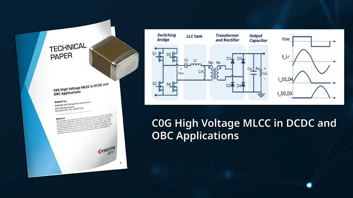
This white paper written by Robert Lu, KYOCERA AVX, discusses the advantages of C0G high voltage MLCC ceramic capacitors when compared to film capacitors in DC/DC and On Board Chargers (OBC).

Capacitance stability is paramount when selecting the appropriate resonant capacitor for resonant circuits. Desirable characteristics include minimal variations with temperature, voltage, and frequency fluctuations.

RelatedPosts

KYOCERA 10 µF 0201 MLCC Brings High‑Capacitance into Mobile Designs

KYOCERA AVX Extends MLV Varistors for 48V Automotive Protection

Kyocera Developed Multilayer Ceramic Core Substrate for AI Packages

While film capacitors offer a suitable option for certain applications, advancements in Micro-Laminated Ceramic Capacitor (MLCC) technology have enhanced the performance of other capacitor dielectrics.

In DC-DC/OBC applications, C0G High Voltage MLCCs emerge as a more suitable choice compared to film capacitors. They exhibit minimal capacitance variation with temperature and possess a low DF dissipation factor at high frequencies.

Understanding DC-DC And OBC LLC Circuit

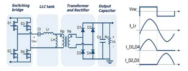
In a DC-DC converter, the LLC resonant circuit efficiently converts the DC voltage to the desired output voltage. When the switching MOSFET is on, it applies the supply voltage to the resonant inductor, storing energy. Conversely, when the MOSFET is off, the inductor releases this energy, which is then transferred to the load through the resonant capacitor. By controlling the MOSFET’s on-off time, the output voltage can be adjusted.

further reference: LLC Resonant Converter Design and Calculation

In on-board chargers (OBCs), the LLC resonant circuit plays a crucial role in converting the input alternating current into direct current to charge the battery of an electric vehicle (EV). Similar to DC-DC converters, the LLC resonant circuit regulates the output voltage by controlling the MOSFET’s on-off time.

One of the key advantages of the LLC resonant circuit is the zero voltage on (ZVS) of the two main MOS switches on the primary side and the zero current off (ZCS) of the secondary rectifier diode. This soft switching technology significantly reduces the power supply’s switching losses, enhancing the converter’s efficiency and power density. Additionally, the LLC resonant circuit ensures constant output voltage, improving the stability and reliability of the power supply.

As illustrated in Figure 1, Lr and Lm represent the leakage inductance and excitation magnetic inductance of the transformer. These inductances, along with the capacitor Cr, form a resonant circuit. The LLC converter comprises two inductors (Lr, Lm) and a capacitor (C), where the resonant capacitor is connected in series with the transformer. This configuration is also known as a series resonance circuit.

In contrast to the common DC-DC converter, which employs pulse amplitude modulation (PAM) mode to achieve the desired output voltage, the LLC converter utilizes pulse frequency modulation (PFM) mode. In PFM mode, the pulse amplitude remains constant while controlling the switching frequency. Therefore, the resonant capacitors must possess specific characteristics to operate effectively in this mode.

Figure 1. Full-bridge LLC converter with Full-bridge rectifier circuit

C0G High Voltage MLCCs Replace Film Capacitors In DC-DC/OBC LLC Circuit

The usual working voltage in DC-DC/OBC applications ranges from 0-400V, with peak voltage at 450V, and working frequency higher than 100khz. The capacitance stability is a crucial element when considering the right resonant capacitor for resonant circuits; minimum variations with shifts in temperature, voltage, and frequency fluctuation are required.

When subjected to the larger rectangular waveform of voltage, the resonant capacitor must endure a consistent high AC voltage, enabling the LLC converter to transfer power. The high ripple current flowing through the resonant capacitor requires appropriate equivalent series resistance (ESR).

Film capacitors (film caps) have represented the common choice, fitting the requirements when considering voltage, capacitance, ESR value, and temperature, with a rated voltage of 600-1000 V and capacitance of 1-10µf. The common dielectrics for film caps include Polyester, PET (polyethyleneterephthalate) and PP (polypropylene).

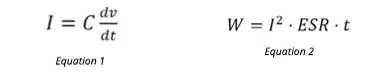
When choosing film caps, the dv/dt value should be taken into account (Equation 1). Standard values in the industry include AC 50hz/380v with a maximum dv/dt value at 0.027 V/µs. A 0.47µF capacitor under 500v/µs dv/dt pulse generates 235 A current. Stacked film cap with 5mm lead spacing can handle around 800v/µs dv/dt. The failure mechanism of film caps is not suited for fast dv/dt even with the ESR value at less than 10 mΩ (Equation 2). In some applications with a rapid increase in high current generate extremely high heat, which softens and melts the film cap’s dielectrics. This contributes to a decrease in infrared radiation and thermal failure.

Other weaknesses of film caps include:

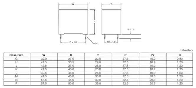
  1. Size: The film cap’s box-like shape takes up considerable room on the PCB (typical dimensions shown in Figure 2)
  2. Wave soldering: The film cap’s leads requires wave soldering during PCBA, potentially interfering with the customer’s manufacturing process
Figure 2. Film capacitor typical dimensions

Despite its limitations, finding a suitable replacement for film capacitors proved to be a significant challenge in the past. Initially, the C0G (NP0) dielectric material was not an ideal choice due to its low permittivity, which limited the production of high capacitance capacitors with high voltage. However, advancements in MLCC technology have since improved the capabilities of NP0 high voltage MLCCs, enabling them to accommodate higher capacitance and voltage within a compact size. This has made them an effective replacement for film capacitors.

As the demand for smaller and more powerful DC-DC/OBCs continues to grow, customers are increasingly seeking a higher power-to-density ratio. Engineers recognize the advantages of high voltage C0G MLCCs packaged in miniature sizes compared to film capacitors.

C0G MLCCs remain a viable option as electric vehicles and other applications increasingly adopt wide-bandgap (WBG) semiconductor technologies such as SiC and GaN. Unlike MOSFETs with a typical working frequency of around 100-300 kHz, WBG semiconductors operate at higher frequencies, with SiC reaching 500 kHz and GaN reaching 1 MHz. In such high-frequency applications involving SiC and GaN semiconductors and temperatures exceeding 150°C, C0G MLCCs often outperform film capacitors.

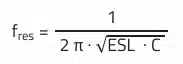
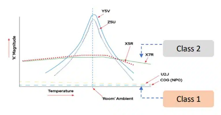
In resonant circuits, Class 1 ceramic materials like NP0 and U2J dielectrics offer the best performance compared to second-class materials like X7R. NP0 and U2J exhibit minimal capacitance variation with temperature and low dissipation factor at high frequencies (Figure 3, Equation 3). Conversely, the dissipation factor of X7R MLCCs increases steadily with frequency, leading to potential failure due to heat generation.

Equation 3. Series resonance frequency
Figure 3. Capacitance stability of different dielectrics

C0G High Voltage MLCC Solution

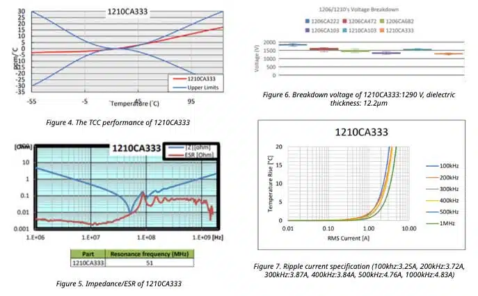
C0G (NP0) ceramic capacitors are perfect for applications that demand high stability and minimal losses due to their temperature coefficient of capacitance of ±30ppm/°C. They maintain their stability across a broad temperature range. The C0G high-voltage MLCC is made of Strontium Calcium Zirconium Titanate (SCZT), which has a permittivity of 20-30.

In DC-DC/OBC applications, common sizes of C0G high-voltage MLCCs include 1206, 1210, and 2220, with voltage ranges from 630 to 1000 V. These capacitors perform better at higher capacitance values.

To select the optimal capacitor, customers first calculate the total voltage and capacitance required. Engineers then determine the number of capacitors needed in series to achieve the target voltage and the number needed in parallel to increase the capacitance. To simplify the design, they choose a single type of capacitor, such as the 1210CA333J4T2A. Finally, they design and connect the capacitors to meet the desired voltage and capacitance requirements.

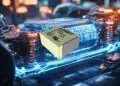
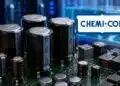
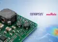
The 1210CA333J4T2A example (Figures 4-7) exemplifies the quality of KYOCERA AVX’s C0G high-voltage MLCC. In DC-DC/OBC applications, this process for selecting capacitors makes C0G high-voltage MLCC an attractive option because other resonant capacitors may necessitate the use of balance resistors, leading to increased costs and circuit complexity. Ensuring the quality and reliability of resonant capacitors is paramount to customers.

The KYOCERA AVX C0G high-voltage MLCC not only offers a suitable choice for DC-DC/OBC applications but also guarantees customers high-quality and reliable capacitors.


Related

Source: KYOCERA AVX

Recent Posts

YAGEO Introduces 310VAC SMD Y2 Safety MP Capacitors for Compact EMI Filtering

16.6.2026
2

DMASS: European Components Distribution Returns To Growth In Q1 2026

16.6.2026
6

German Component Distribution Market Rebounds in Q1 2026 According to FBDi

16.6.2026
6

Nippon Chemi-Con Announces New Capacitor series for AI, Automotive and Immersion Cooling

16.6.2026
10

Ultrahigh Energy Storage in Lead‑Free BiFeO₃‑Based Ceramic Capacitors via Local Polar Structure Design

16.6.2026
11

Murata Expands Ansys Simulation Models for RF inductors, MLCCs, and Power Inductors

16.6.2026
9

Sumida Introduces SMD Metal Inductors for High‑Current Automotive DC/DC Converters

15.6.2026
14

Knowles Releases 3825 X1/Y2 Safety MLCCs for High‑Voltage Applications

11.6.2026
35

TAIYO YUDEN Releases 220uF 1210 Automotive MLCC

11.6.2026
49

Upcoming Events

Jul 14
16:00 - 17:00 CEST

EMC Design Essentials: Mastering Varistors and Common Mode Chokes

Jul 21
16:00 - 17:00 CEST

Safety by design: X and Y Interference suppression capacitors for power line filters

View Calendar

Popular Posts

  • Buck Converter Design and Calculation

    0 shares
    Share 0 Tweet 0
  • Boost Converter Design and Calculation

    0 shares
    Share 0 Tweet 0
  • LLC Resonant Converter Design and Calculation

    0 shares
    Share 0 Tweet 0
  • MLCC and Ceramic Capacitors

    0 shares
    Share 0 Tweet 0
  • Flyback Converter Design and Calculation

    0 shares
    Share 0 Tweet 0
  • Earthing Systems and IEC Classification Explained

    0 shares
    Share 0 Tweet 0
  • SEPIC Converter Design and Calculation

    0 shares
    Share 0 Tweet 0
  • Dual Active Bridge (DAB) Topology

    0 shares
    Share 0 Tweet 0
  • What Electronics Engineer Needs to Know About Passive Low Pass Filters

    0 shares
    Share 0 Tweet 0
  • MLCC Case Sizes Standards Explained

    0 shares
    Share 0 Tweet 0

Newsletter Subscription


Passive Components Blog

© EPCI - Leading Passive Components Educational and Information Site

  • Home
  • Privacy Policy
  • EPCI Membership & Advertisement
  • About

No Result
View All Result
  • Home
  • Knowledge Blog
  • Dossiers
  • PCNS

© EPCI - Leading Passive Components Educational and Information Site

This website uses cookies. By continuing to use this website you are giving consent to cookies being used. Visit our Privacy and Cookie Policy.
Go to mobile version