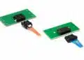


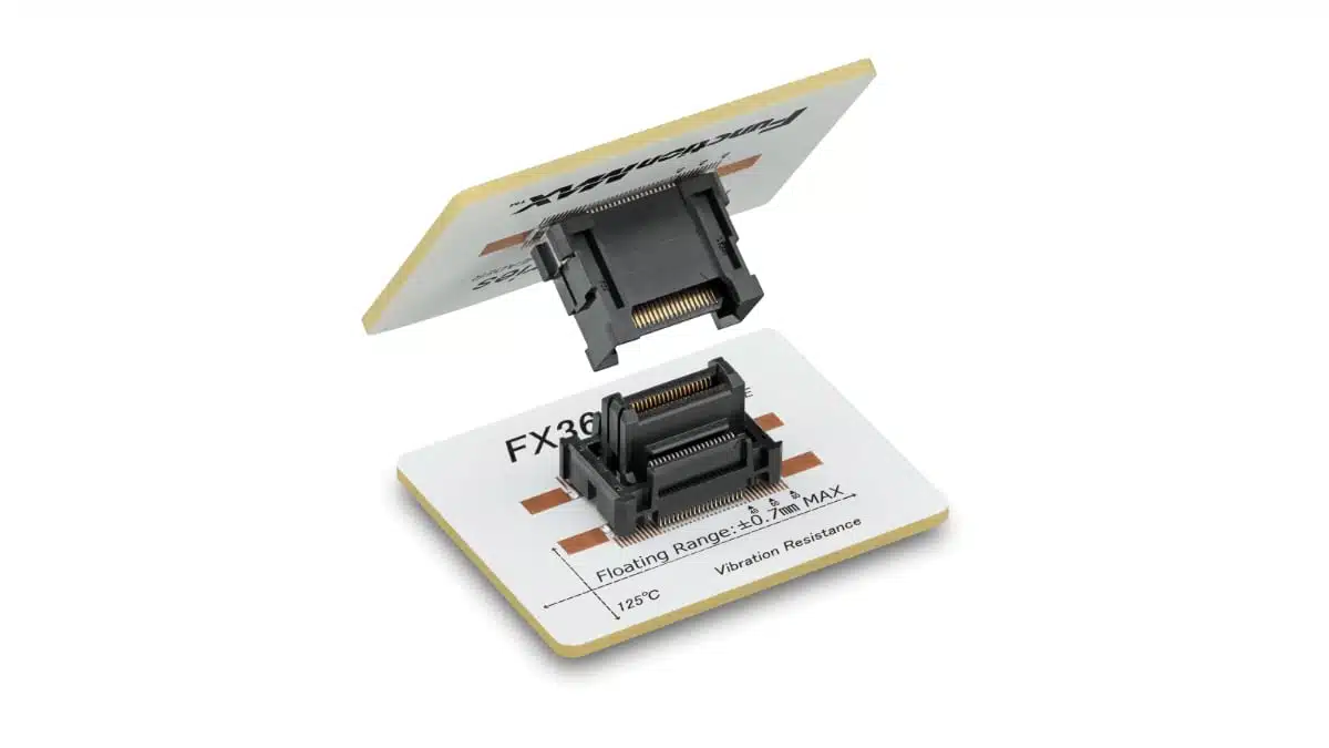
Hirose Electric’s new FX36 series is a 0.5 mm pitch board-to-board connector with a floating and vibration absorption structure designed for harsh automotive powertrain environments.
It targets BEV/HEV inverters, converters, onboard chargers, and X‑in‑1 units where high-temperature operation, vibration robustness, and dense packaging are critical for reliable system performance.
Key features and benefits
- 0.5 mm pitch for high-density layouts
The fine pitch and compact form factor support tighter board spacing and higher functional integration in confined powertrain enclosures, helping shrink X‑in‑1 units and domain controllers without reverting to cable harnesses. - Floating mechanism for misalignment tolerance
The connector allows relative board movement of ±0.7 mm in both X and Y directions and an effective mating length of ±0.5 mm in Z, improving assembly yield and making it more forgiving to PCB tolerance stack‑ups and automated assembly variation. - Vibration absorption structure in Z direction
A dedicated vibration absorption design attenuates PCB amplitude in the mating (Z) direction with a specified total absorption of 0.05 mm during operation, which helps maintain stable contact in high‑vibration automotive environments. - High-temperature capability up to 125 °C
The series is specified for 125 °C heat resistance, aligning with typical automotive under‑hood temperature profiles and enabling use near inverters, DC/DC converters, and power modules without derating the connector below system needs. - Two-point contact for reliability
A two-point contact structure provides redundant contact paths per signal, improving robustness against micro‑fretting, slight contamination, or minute PCB movement over the vehicle lifetime. - Space and weight reduction compared to cables
By replacing cable harnesses with a rigid board-to-board interface, the FX36 can contribute to lower harness weight, reduced assembly steps, and cleaner internal layouts in powertrain modules.
Typical applications
The FX36 series is positioned for electrified powertrain and control electronics, especially where functions are consolidated into multi‑function modules.
- X‑in‑1 powertrain units (e.g., combined inverter, DC/DC, onboard charger) in BEVs and HEVs, where multiple power and control boards must be interconnected in a compact, high‑temperature housing.
- Traction inverters and converters for large drive motors, building on Hirose’s FX26 deployment track record but with finer pitch for denser layouts.
- Onboard chargers and auxiliary power converters that require high‑reliability interconnects between power stages, control boards, and sensor boards.
- Electric power steering (EPS) ECUs with tight packaging and severe vibration exposure.
- Domain controllers and other high-integration control units where multiple PCBs are stacked or placed in close proximity and subjected to automotive temperature and vibration profiles.
For purchasing and design teams, the FX36 can be considered as a candidate wherever a legacy cable-based connection is used between stacked or parallel boards, especially when weight reduction, automated assembly, or envelope reduction is a project KPI.
Technical highlights
The press release provides a qualitative focus on mechanical and environmental performance; detailed electrical ratings should be taken from the official datasheet according to manufacturer documentation.
Floating and vibration specifications
| Parameter | FX36 specification |
|---|---|
| Pitch | 0.5 mm |
| Floating range in X direction | ±0.7 mm |
| Floating range in Y direction | ±0.7 mm |
| Effective mating length in Z direction | ±0.5 mm |
| Z‑direction PCB amplitude absorption | 0.05 mm (during operation) |
| Maximum heat resistance | 125 °C |
The combination of floating misalignment tolerance and a defined Z‑direction absorption allows the connector to follow relative board motion induced by vibration or thermal expansion without overstressing solder joints or contact beams.
Pin counts and stacking heights
Hirose indicates both current mass‑production options and planned expansions for the series.
| Status | Pin counts | Stacking heights |
|---|---|---|
| Mass production | 40 positions | 20 mm |
| Under development | 40, 50, 60, 80 pos. | 15, 18, 20 mm |
For design‑in, this means early projects can start with a 40‑position, 20 mm height configuration while keeping migration paths open to higher pin counts and alternative stack heights as the lineup expands.
Environmental and mechanical focus
- Target environment: Automotive powertrain and harsh vibration conditions, especially in BEVs and HEVs.
- Legacy reference: Builds on the FX26 (1.0 mm pitch) platform, known for high heat resistance and vibration performance in large motor inverters and converters.
- Application goal: Enable further miniaturization, weight reduction, and more efficient automated assembly processes compared to cable‑based interconnects.
Exact current, voltage, and insulation specifications are to be taken from the FX36 series datasheet and design guides according to manufacturer datasheet, as these are not fully detailed in the press release.
Design-in notes for engineers
- Treat FX36 as a mechanical and thermal design element, not just a connector
The floating mechanism and Z‑direction absorption rely on correct board‑to‑board spacing and mechanical support; ensure the specified stacking height and tolerance window are respected so that the floating range is fully functional in X, Y, and Z. - Co‑design with PCB tolerances and assembly process
The ±0.7 mm floating in X and Y can relax some tolerance stack‑ups, but it should not be used to compensate for poor PCB registration; instead, factor it into panel design, fiducial placement, and pick‑and‑place accuracy to balance yield and robustness. - Consider vibration modes and board stiffness
Since the vibration absorption structure is oriented in the mating direction, board stiffness, mounting points, and enclosure layout should be designed so that most relative motion between boards is along Z, allowing the connector’s absorption to be fully utilized. - Thermal environment and derating
With a 125 °C heat resistance rating, the FX36 is suitable for many under‑hood and powertrain zones, but designers should still perform thermal simulations and measurements around the connector region and apply current and temperature derating from the datasheet according to manufacturer datasheet. - Signal integrity and creepage/clearance
The 0.5 mm pitch supports dense pin mapping; when routing high‑voltage or high‑speed signals, carefully allocate pins and reference grounds to meet creepage/clearance requirements and maintain signal integrity, especially in inverter and DC/DC platforms. - Migration from FX26 or cable harnesses
For projects currently using FX26 (1.0 mm pitch) or cable harnesses, an architectural review can identify where FX36 enables further stacking height optimization and footprint reduction, while maintaining similar vibration performance characteristics. - Lifecycle and future variants
Because Hirose plans to expand pin counts and heights, system architects may reserve board keep‑out areas and mechanical envelope margins to accommodate future FX36 variants if pin count needs are expected to grow. - Testing and validation
As with any safety‑relevant powertrain interconnect, laboratory validation should include thermal cycling, random vibration, shock, and combined environment tests aligned with OEM requirements, leveraging FX36’s intended use in high‑vibration, high‑temperature applications.
Source
This article is based on Hirose Electric’s official press release and related FX36 series product information, interpreted from an independent technical perspective for design and procurement engineers.