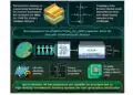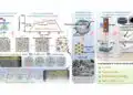
Imec has extended its 300 mm RF silicon interposer platform with high‑density metal–insulator–metal capacitors (MIMCAPs), a scalable passive modeling framework and laser‑assisted chiplet bonding to support heterogeneous integration of III‑V chiplets on Si‑CMOS.
These advances target next‑generation mmWave and sub‑THz wireless front‑ends and RF‑grade signal handling in data‑center links, where compact, low‑loss passives and predictable high‑frequency behavior are critical for system‑in‑package design.
Key features and benefits
- High‑density embedded MIM capacitors in the interposer
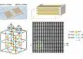
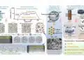
The interposer integrates MIM capacitors that use a high‑k aluminum‑hafnium‑oxide dielectric combined with three‑dimensional oxide‑stud structures in the back‑end‑of‑line stack, achieving a 10‑ to 100‑fold increase in capacitance density versus typical on‑chip capacitors in III‑V processes. This significantly increases decoupling capacitance per unit area, enabling designers to offload large on‑chip capacitors and shrink III‑V die area and cost while maintaining power integrity for mmWave and sub‑THz building blocks. - Offloading passives from III‑V chiplets
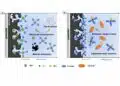
Decoupling capacitors and other passives can be moved from III‑V chiplets into the RF silicon interposer, freeing up valuable chiplet area and allowing III‑V dies to focus on gain and power devices. This partitioning is particularly attractive for expensive III‑V technologies such as InP, GaAs and GaN, where every square millimeter of die area carries a premium. - RF‑optimized low‑loss interposer platform
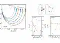
The interposer provides low‑loss transmission lines and hosts passive networks while III‑V chiplets implement performance‑critical active functions. Previous iterations of the platform have demonstrated negligible insertion loss at 140 GHz and record‑low loss up to 325 GHz, and the latest work builds on that foundation by adding compact MIMCAPs and better passive modeling for system‑level design. - Scalable passive modeling framework up to sub‑THz
A modeling framework for RF passives on the interposer has been validated up to approximately 300 GHz, enabling designers to predict how circuit performance evolves as geometries and layouts change without re‑simulating or re‑measuring every variant. This shortens design cycles and supports parametric optimization of transmission lines, inductors and MIM capacitors for different frequency bands and applications. - Laser‑assisted chiplet bonding with tight alignment
Laser‑assisted bonding achieves sub‑600 nm alignment accuracy and less than 0.05° rotational misalignment across 43 devices when attaching III‑V chiplets onto the passive‑rich RF interposer. This approach supports assembly on complex stacks without exceeding thermal budgets or damaging temperature‑sensitive interposer layers, which is essential for keeping BEOL integrity and high‑k dielectrics intact during packaging. - Verified RF performance after assembly
RF measurements on assembled demonstrators show reflection below −15 dB in the 110–170 GHz range, indicating that the combined interposer, passives and laser‑bonded chiplets can support high‑frequency operation with acceptable return loss. For system designers, this demonstrates that heterogeneous chiplet integration on a passive‑rich interposer can meet stringent RF performance requirements while enabling more compact modules.
Typical applications
The platform targets high‑frequency RF systems where a combination of compact passives, predictable layout‑dependent behavior and advanced packaging is needed.
- mmWave and sub‑THz wireless front‑ends for beyond‑5G and early 6G systems, where phased‑array beamforming, power amplifiers and up/down‑conversion benefit from compact decoupling and low‑loss interconnects at D‑band and above.
- High‑speed data‑center links where electronic and photonic interfaces are reaching electrical limits, and RF‑grade signal handling on interposers helps bridge between CMOS, III‑V and photonic dies at hundreds of gigahertz.
- Multi‑chip RF front‑end modules combining III‑V power devices (GaN or GaAs), InP low‑noise stages and Si‑CMOS control or beamforming ASICs on a shared interposer with integrated passives.
- Heterogeneous RF system‑in‑package designs where designers want to decouple passive networks from expensive III‑V processes and instead implement them on a reusable silicon interposer platform.
System‑level integration scenarios
- Partitioning large decoupling capacitor banks for power delivery networks between the interposer and the chiplets, so that the interposer provides bulk capacitance and the III‑V chips only implement local high‑frequency decoupling where necessary.
- Implementing matched transmission lines and passive matching networks on the interposer, with the passive modeling framework providing layout‑aware models, while III‑V dies handle active gain stages and power amplification at mmWave bands.
- Co‑integrating RF and optical components for short‑reach links, where RF signal conditioning and passive networks reside on the interposer alongside photonic dies and CMOS driver/receiver ASICs.
Technical highlights
The main technical elements of the updated RF interposer platform are summarized in the table below.
| Parameter / feature | Value / description |
|---|---|
| Interposer wafer size | 300 mm RF silicon interposer platform |
| Integrated passive type | High‑density metal–insulator–metal (MIM) capacitors |
| MIM dielectric | High‑k aluminum‑hafnium‑oxide |
| MIM structure | Three‑dimensional oxide‑stud BEOL architecture |
| Capacitance density gain | 10–100× versus typical on‑chip III‑V capacitors |
| Frequency range of passive modeling | Validated up to approximately 300 GHz (sub‑THz regime) |
| Targeted passives in modeling framework | Transmission lines initially, extending to inductors and MIM capacitors |
| Chiplet technology | III‑V materials such as InP, GaAs and GaN on Si‑CMOS |
| Chiplet assembly method | Laser‑assisted bonding on RF silicon interposer |
| Alignment accuracy (linear) | Below 600 nm across demonstrated devices |
| Alignment accuracy (rotational) | Below 0.05° across demonstrated devices |
| Measured reflection after assembly | Better than −15 dB in the 110–170 GHz range |
All values and qualitative descriptions in this table follow the press information and should be cross‑checked against the corresponding technical papers and datasheets for design‑in.
MIM capacitor architecture
The MIM capacitors use a high‑k aluminum‑hafnium‑oxide dielectric, which increases capacitance per unit area by providing a higher permittivity than conventional silicon dioxide‑based stacks. In practice, this means that for a given footprint, engineers can realize more decoupling capacitance or, conversely, achieve the same capacitance in a smaller area compared to standard on‑chip III‑V capacitors.
The introduction of three‑dimensional oxide‑stud structures in the BEOL effectively increases the effective electrode surface area within the same planar footprint. For RF and power‑integrity engineers, this 3D approach combines high capacitance density with a layout that remains compatible with back‑end routing, making it suitable for dense RF interposer designs.
Passive modeling framework
Imec has developed and validated a modeling framework for RF passives on the silicon interposer up to roughly 300 GHz. This framework enables parametric models that capture the dependence of passive behavior on geometry and layout, allowing designers to explore design spaces without running a full electromagnetic simulation for every variant.
Initially focused on transmission lines, the framework forms the basis of a design library that is being extended to include inductors and MIM capacitors. For mmWave and sub‑THz co‑design, this offers a more predictable path from schematic to layout, supporting both circuit‑level simulation and system‑level exploration of different interposer configurations.
Laser‑assisted bonding details
Laser‑assisted bonding is used to attach III‑V chiplets onto the RF silicon interposer while managing thermal exposure of sensitive interposer layers. The localized energy input of the laser helps achieve good bonding quality and alignment without subjecting the entire assembly to high‑temperature profiles that might damage high‑k dielectrics or delicate BEOL structures.
Demonstrated devices show sub‑600 nm linear alignment accuracy and less than 0.05° rotational misalignment across 43 bonded chiplets, indicating that the process can support dense multi‑chip layouts. Reflection measurements below −15 dB from 110 to 170 GHz confirm that RF performance remains within acceptable limits after bonding, which is crucial for high‑frequency signal paths.
Availability and ecosystem
The RF silicon interposer platform is presented as an evolving system‑level technology rather than an off‑the‑shelf catalog component. Imec positions it within its R&D programs and collaborations, supporting partners who are developing beyond‑5G, 6G and high‑speed data‑communication systems.
Source
This article is based on an imec press release announcing advances to its 300 mm RF silicon interposer platform, complemented by related imec publications referenced by the manufacturer. For precise numerical limits and design constraints, engineers should refer to the corresponding imec technical papers and process documentation.
References
- Imec press release: Imec unlocks system-level III-V chiplet integration on Si-CMOS by advancing its 300mm RF silicon interposer platform with high-density MIMCAPs, passive modeling, and laser-assisted bonding
- Seamless InP chiplet integration on 300mm RF silicon interposer (related earlier press release)
- Record-low insertion loss of 300mm RF silicon interposer platform (related earlier press release)