


Modern power electronics design relies on a diverse toolbox, from general‑purpose circuit simulators to highly specialized magnetics and component‑selection platforms. Understanding the role and limitations of these tools is essential when specifying passive components such as inductors, transformers, capacitors, and resistors in a cost‑sensitive, time‑critical design flow.
This article is based on edited newsletter article by Dr.Molina, Frenetic CEO.
Key Takeaways
- Understanding modeling tools for passive components is crucial for efficient power electronics design.
- Various tools, including general-purpose SPICE simulators and specialized magnetics design tools, aid in selecting and sizing passive components.
- Parameters like core shape, wire gauge, and capacitor specifications significantly influence design outcomes.
- Emerging AI-native workflows aim to unify power electronics design by integrating topology selection and optimization.
- A coherent workflow linking these tool classes ensures traceability and alignment with cost and reliability targets.
From topology to real components
Power converter development typically follows a workflow: requirements gathering, specification, topology selection, simulation, component design/selection, and finally schematic capture and PCB layout. The tools reviewed in this article sit mainly in the topology evaluation, circuit simulation, and component design/selection stages, where they strongly influence passive component sizing, stress margins, and BOM structure.
A key takeaway is that no single environment covers everything from first‑principles magnetics design to detailed PCB‑level parasitics and full BOM optimization. Instead, design teams usually combine several tools: one or more simulators for behavior and losses, parametric selectors from major semiconductor manufacturers, and specialized magnetics design suites for custom inductors and transformers.
Key categories of tools
General‑purpose circuit simulators
These are SPICE‑class environments used heavily for SMPS and analog design, often forming the “backbone” of a lab’s simulation flow.
- LTspice (Analog Devices) is a widely adopted, free desktop simulator used for switching power supplies and analog circuits. It offers strong convergence, a large ecosystem of models, and community support, but has limited integration with PCB and component management tools and a dated user interface.
- PSpice/OrCAD‑class environments provide more extensive enterprise workflows, combining schematic, PCB, and BOM management with powerful simulation features at a higher licensing cost and complexity.
For passive components, these tools are typically used to verify voltage and current waveforms across inductors, transformers, capacitors, and resistors, evaluate losses, and check stability margins before hardware builds.
Power‑electronics‑focused simulators
Some simulators are optimized specifically for SMPS and converter behavior, trading transistor‑level detail for speed and robustness in switching applications.
- PSIM (Siemens, originally Powersim) is a long‑standing power‑electronics‑focused circuit simulator, widely used in both industry and education. It is noted for very easy use, fast convergence in switching converters, and suitability for rapid topology evaluation, but has less detailed device‑level models than SPICE.
- PLECS focuses strongly on control‑loop design and system‑level modeling of power converters. It is not intended for device‑level transistor simulation but excels at power stage plus control interaction and is often coupled with external magnetics tools.
- SIMPLIS is positioned as a converter design and verification platform, integrating switching power supply simulation with time‑domain efficiency and strong control features. It emphasizes schematics that closely resemble real SMPS circuits and very fast convergence, with licensing based on an initial fee plus annual updates.
For passive components, these platforms help determine worst‑case stress, verify soft‑switching or hard‑switching regimes in inductors and transformers, and validate the interaction between magnetics, capacitors, and control loops before committing to a custom core or winding strategy.
Parametric selectors from manufacturers
Most semiconductor and magnetics manufacturers offer online parametric tools for device selection, covering power MOSFETs, diodes, inductors, and sometimes transformers.
These web‑based tools allow engineers to filter components by voltage rating, current, core material, saturation limits, package, DC resistance, and other key parameters. They are particularly helpful at the early selection stage, ensuring that candidate passives meet headline electrical and thermal constraints before detailed simulation and layout.
However, parametric selectors are typically vendor‑specific, limited to that supplier’s catalog, and rarely integrate deeply with schematic, simulation, or PCB environments. They are best treated as a starting point for a longlist of feasible parts, which are then refined using more detailed simulation and magnetics design tools.
Online calculators
Online calculators—such as core sizing tools, loss estimators, and basic inductor/transformer calculators—remain widely used, especially by younger engineers or for quick cross‑checks.
They help validate first‑order design equations and offer sanity checks on core size, turns count, and current density. Their main limitation is isolation from the wider design flow: they usually do not “know” about the actual waveforms, duty cycles, or control strategy in the real converter, so their results must be validated in a full simulator.
Simulators and their role for passives.
| Tool | Type | Main purpose in passives work | Typical use in flow |
|---|---|---|---|
| LTspice | General‑purpose SPICE simulator | Waveform‑level validation of stress on inductors, caps, resistors | Concept validation, detailed circuit analysis |
| PSIM | Power‑electronics‑focused simulator | Fast topology evaluation, converter‑level loss and stress analysis | Architecture selection, education, early design |
| PLECS | Power‑electronics/system simulator | Control‑loop and system‑level interaction with magnetics and caps | Control design, system studies |
| SIMPLIS | Converter design and verification | SMPS behavior, time‑domain efficiency, magnetics plus control checks | Design verification before hardware |
Specialized magnetics design tools
Legacy but proven: RidleyWorks
RidleyWorks is a long‑standing power supply design and analysis package with a strong following among SMPS designers. It spans topology selection, loop analysis, and magnetics design, using an Excel‑based interface with macros for data entry and calculations.
- Strengths: Mature models, particularly for control‑loop estimation; solid reputation in the community; used in real industrial environments.
- Limitations: Many models are based on the historical work of the tool’s author, while magnetics modeling techniques and materials have evolved significantly in the last two decades; project storage is rudimentary, often requiring screenshots or manual archiving.
For passive components, RidleyWorks is valuable for loop‑stability analysis, compensation design, and power stage parameterization, which indirectly drives capacitor ESR and inductor/transformer design targets.
High‑fidelity physics: COMSOL and similar FEA
Finite‑element tools such as COMSOL (mentioned in the article series) are typically used as the “physics validation” stage once a baseline design exists. They are particularly relevant when:
- Winding arrangements and leakage inductance must be tightly controlled.
- Core losses and hot spots need 3D evaluation.
- Very high efficiency, high power density, or unusual core shapes are required.
In a passive component context, FEA tools are best reserved for critical or custom magnetics where traditional lumped‑parameter models are insufficient, due to cost, setup effort, and required expertise.
Workflow‑centric tools: SIMPLIS with Magnetics Design Module
Beyond pure simulation, platforms like SIMPLIS extend into magnetics sizing through dedicated modules. Its Magnetics Design Module (MDM) and Design Verification Module (DVM) allow engineers to design and size inductors and transformers in the context of the full converter, rather than as standalone calculations.
This workflow checks operating points, stresses, waveforms, and margins against design rules, effectively answering whether the design works—not just what the waveforms look like. For passive components, this is a major step toward “model‑based” magnetics design integrated with system‑level performance.
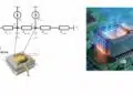
Cloud‑based magnetics design: Frenetic
Frenetic is an online tool for designing and simulating transformers and inductors, with a workflow centered on cloud‑based projects and collaboration.
- It provides topology‑based templates and lets users define constraints (power, frequency, size, thermal limits) to synthesize magnetics that meet those targets.
- Designs are stored in the cloud under defined security standards, enabling team access and versioning.
For passive component engineers, Frenetic’s main value lies in accelerating custom magnetics design, exploring multiple core and winding configurations, and converging quickly on manufacturable solutions that meet specified losses and temperature rise limits.
Magnetics‑focused tools
| Tool | Focus area | Typical passive decisions supported | When to prefer it |
|---|---|---|---|
| RidleyWorks | SMPS design and loop analysis | Inductor and transformer sizing linked to control stability | When loop design and legacy workflows matter |
| COMSOL | 3D physics / FEA | Detailed core/copper loss and hot‑spot analysis | When operating near physical limits |
| SIMPLIS MDM | Integrated magnetics design | Core selection, turns, winding layout in full‑circuit context | When converter and magnetics are tightly coupled |
| Frenetic | Cloud magnetics synthesis | Core selection, window use, thermal and loss trade‑offs | When fast custom magnetics iterations are needed |
Typical applications and tool fit
Different stages of a power converter design call for different tool capabilities, particularly when passive components dominate cost, volume, and reliability.
- PFC stages and DC link: Power‑electronics‑focused simulators (PSIM, PLECS, SIMPLIS) and SPICE tools (LTspice) are commonly used to size boost inductors, DC‑link capacitors, and EMI filters, by checking current ripple, harmonic content, and stress under line/load extremes.
- Isolated DC/DC converters: Magnetics design tools (RidleyWorks, Frenetic, SIMPLIS MDM) help design transformers and output inductors to meet isolation and efficiency targets, while general simulators validate control loop stability and transient behavior.
- Automotive ECUs and industrial drives: Tight EMI and thermal constraints make parametric selectors and detailed magnetics tools essential, as designers must combine catalog filters, physics‑based evaluation, and system‑level simulation to meet safety and reliability standards.
- Chargers and adapters: High volume and aggressive cost targets favor workflows where parametric selectors, online calculators, and fast simulators are used to rapidly iterate magnetics and capacitor options, with FEA reserved only for reference or flagship designs.
Example: workflow versus passive decisions.
| Design stage | Representative tools | Main passive‑related decisions |
|---|---|---|
| Topology exploration | LTspice, PSIM, PLECS, SIMPLIS | Inductor/transformer energy storage, ripple, basic sizing |
| Magnetics synthesis | RidleyWorks, SIMPLIS MDM, Frenetic | Core, turns, wire, loss balance, thermal limits |
| Physics validation | COMSOL or similar FEA | Field distribution, hot spots, leakage, advanced EMI |
| Final sign‑off | SIMPLIS, SPICE tools plus FEA if needed | Margin to ratings, lifetime, worst‑case behavior |
Technical highlights relevant to passive components
What the tools actually decide
While the tools in this series vary widely in scope, for passive components they influence a common set of decisions:
- Core shape, material, and size for inductors and transformers.
- Number of turns, wire gauge, and layering to balance copper loss, leakage, and manufacturability.
- Capacitance, voltage rating, ESR/ESL, and package for DC‑link and output capacitors.
- Resistor ratings and networks used for sensing, damping, and snubbing.
Workflow‑centric tools like SIMPLIS with MDM, and cloud platforms like Frenetic, are particularly focused on embedding these decisions into a systematic process, rather than treating magnetics as isolated spreadsheets.
Accuracy versus speed trade‑offs
Simulation environments vary significantly in their modeling depth and runtime:
- SPICE‑class tools provide high fidelity for device‑level behavior but may require careful tuning for convergence in complex switching circuits.
- Power‑electronics‑focused simulators aim for robust and fast convergence with simplified device models, ideal for exploring topologies and doing sensitivity analysis on passive values.
- Magnetics design suites and FEA tools emphasize accurate core and copper loss estimation, field distribution, and thermal behavior, at the cost of higher setup complexity and runtime.
In practice, design teams often accept lower fidelity in early architectural studies and parametric sweeps, moving to higher‑fidelity magnetics or FEA tools only once a promising design has been identified.
AI agents for magnetic and passive design
Most of the value in AI for power electronics sits in how well the agent understands magnetics and passives, not just topologies. Beyond sizing a transformer or inductor from simple rules of thumb, an AI agent can search a large design space of core shapes, materials, and winding strategies while respecting EMI, thermal limits, and manufacturability. For capacitors and resistors, it can do something similar by balancing ripple, lifetime, and cost across thousands of catalogue parts instead of a short human‑curated shortlist.
In practice this means: you describe power level, topology, cooling constraints, isolation requirements, and mechanical envelope in text; the agent decomposes this into a series of design problems and calls specialized calculators and databases. Instead of manually iterating through spreadsheet tabs and manufacturer apps, you get a first feasible magnetics and passives set in minutes, then refine with your engineering judgement.
Example: Frenetic AI in the power‑magnetics loop
Frenetic AI is a good example of where this is already happening in practice. Their agent can propose DC/DC converter designs, generate custom magnetics, and directly output LTspice and KiCad projects for further analysis. From a passives perspective, the interesting piece is that the topology selection, magnetic core choice, and initial winding design are handled by the system, while the engineer focuses on constraints and verification.
Once a candidate transformer or inductor is defined, the same workflow can be extended to suggest suitable capacitors (bulk, decoupling, snubbers) and resistors (sense, damping, dividers) based on voltage stress, ripple current, and lifetime models. The long‑term direction is clear: one agent orchestrates magnetic design, spice model generation, layout‑relevant parasitic estimation, and preliminary BOM creation, all driven from a textual spec.
AI‑assisted selection of catalogue passives
Finding OTS passives is often more time‑consuming than running the simulations themselves. An AI “BOM agent” can take electrical requirements (voltage, current, frequency, lifetime) and mechanical constraints, then search distributors, in‑house ERP, and manufacturer datasheets to propose consistent, sourceable part sets. This is especially useful when you want multi‑sourcing across vendors and packages, or when you must align with company‑specific approved vendor lists.
For magnetics, the same approach can filter standard cores and bobbins before you consider custom parts. For capacitors, it can automatically enforce derating rules per technology (MLCC, electrolytic, film, tantalum), check ripple ratings, and pre‑screen for reliability constraints such as AEC‑Q200. For resistors, it can combine power rating, pulse capability and temperature coefficient rather than treating them as separate filters in a parametric search.
Custom magnetics and manufacturability constraints
Custom magnetics are where today’s design tools often stop and spreadsheets begin. Customization can happen at many levels: core shape and material, gap strategy, winding style (solid, foil, litz), and even hybrid constructions. The limiting factor is not imagination but the ability to calculate parasitics, losses, and manufacturability quickly enough across this design space.
Agentic systems can help by chaining together multiple physics and loss models through APIs, exploring trade‑offs between copper loss, core loss, leakage inductance, and cost. You might specify maximum hot‑spot temperature, allowed interwinding capacitance, and leakage window, and let the agent drive FEM, 1D loss models and cost estimation until it converges on a manufacturable design. The result is not a “black box transformer,” but a parameterized design you can inspect, tweak, and hand over to a magnetics supplier with traceability.
System‑level design: integrating passives into AI workflows
Tools like Celus aim at the system‑design level, from requirements to complete circuit proposals. For passives, this means that instead of dropping default resistor–capacitor values around IC reference designs, the system can reason about control‑loop stability, EMI filters, surge handling, and safety margins automatically. The output is not just a schematic but a set of justifications: why a given EMI filter topology was chosen, why a particular capacitor technology was selected, or how much lifetime margin you have at ambient plus ripple self‑heating.
As these platforms mature, passives will no longer be “filled in later” but will be co‑designed with magnetics, semiconductors, and layout from the first AI‑generated draft. That should reduce late‑stage surprises such as overheating input capacitors or inductors that oscillate with stray capacitances.
PCB layout, parasitics and EMI with AI ECAD
PCB‑centric tools such as Flux AI, JITX and Quilter target the routing and layout side of the workflow. They already use AI to place and route components, check design rules, and optimize cost and area. The next step, very relevant for passives and magnetics, is learning to treat the PCB as part of the magnetic and capacitive structure rather than just a connection medium.
Given a power stage plus magnetics, an AI layout engine can minimize loop areas, control dv/dt and di/dt paths, and place decoupling capacitors to reduce ringing and EMI. With access to FEM or fast field‑solvers, it can estimate parasitic inductances and capacitances of traces, vias and planes and feed them back into updated spice models. This closes the loop between schematic‑level magnetics and passives design and their real‑world behaviour on the PCB.
Hardware validation and test guidance
In the near future the same agent that designed the converter can also supports the lab validation. For passives and magnetics, this is particularly valuable because many field issues show up first as “small” anomalies: slightly elevated temperature, unexpected noise, or marginal waveforms. An AI test assistant can suggest measurement setups, interpret oscilloscope and thermal‑camera captures, and flag patterns that indicate saturation, poor damping, or insufficient derating.
In a more advanced setup, the agent knows the full design history, including how the passive and magnetic values were chosen, and can propose targeted design changes when tests reveal problems. For example, it might recommend a different capacitor technology, a modified snubber network, or a winding rearrangement to fix a specific EMI notch rather than a generic “increase filter size” suggestion.
What this means for passive‑components engineers
If the trajectory sketched above holds, a single engineer with strong domain expertise plus good AI tooling will indeed do the work of a small team. Routine tasks such as initial sizing, catalogue searches, and documentation will be mostly automated, while human effort moves toward defining constraints, validating edge cases, and negotiating trade‑offs with other disciplines.
For engineers working on passives and magnetics, the opportunity is to encode your heuristics and constraints into these AI‑driven workflows instead of fighting them. That can mean building internal calculators and APIs that agents can call, curating high‑quality component data, or contributing to open ecosystems around magnetic and passive models. The teams that combine deep component‑level understanding with agentic automation will set the pace for future power‑electronics design.
Conclusion
Selecting and designing passive components for modern power converters now depends as much on the chosen software toolchain as on the underlying topologies and materials. General‑purpose and power‑electronics‑focused simulators establish realistic electrical stress and operating points, while specialized magnetics tools translate those requirements into manufacturable inductors and transformers.
Manufacturer parametric selectors and online calculators remain useful at the front end of the process, but they must be complemented by integrated simulation and, where necessary, physics‑based FEA to achieve robust, production‑ready designs.
For both engineers and purchasers, the most effective strategy is to build a coherent workflow that links these tool classes, so that every passive component decision—from first sizing to final derating—is traceable, verifiable, and aligned with project cost and reliability targets.
FAQ: Power Electronics Tools for Passives and Magnetics
LTspice is a widely adopted general-purpose SPICE simulator, and PSIM, PLECS, and SIMPLIS as power-electronics-focused simulators that are especially useful for sizing inductors, transformers, capacitors, and EMI filters under realistic switching conditions.
Specialized tools such as RidleyWorks, SIMPLIS Magnetics Design Module, Frenetic, and 3D FEA platforms like COMSOL help engineers choose core shapes and materials, define turns and winding layouts, and evaluate losses and hot spots so that custom inductors and transformers meet electrical, thermal, and EMI requirements.
Manufacturer parametric tools and online calculators are useful for early screening of catalog components and quick sanity checks on ratings and sizes, but the article stresses that their results must be validated in full circuit simulations and, when needed, magnetics or FEA tools before committing to production components.
Combining simulators, magnetics design tools, and validation platforms provide a coherent workflow that ensures that every passive component decision—from first sizing to final derating—is traceable, verifiable, and aligned with project cost, reliability, and EMI targets.
How to select and design passive components using modern power electronics tools
- Step 1 – Define requirements and choose topology
Start by defining input and output specifications, efficiency targets, size limits, and regulatory constraints, then select a suitable converter topology so that subsequent simulations reflect realistic operating conditions and passive stress levels.
- Step 2 – Simulate the converter
Use a SPICE or power-electronics-focused simulator such as LTspice, PSIM, PLECS, or SIMPLIS to model the converter, then extract key waveforms and RMS values for inductors, transformers, capacitors, and resistors, including ripple, peak currents, and voltages across the expected operating range.
- Step 3 – Use parametric tools to shortlist catalog components
With the simulated stresses as a guide, use manufacturer parametric selectors to filter inductors, transformers, and capacitors by voltage rating, current capability, core material, ESR, and package, creating a shortlist of components that meet headline electrical and thermal requirements.
- Step 4 – Design or refine custom magnetics
When catalog parts are insufficient or optimization is needed, use dedicated magnetics tools such as RidleyWorks, SIMPLIS Magnetics Design Module, Frenetic, or FEA platforms to set core type, turns, wire gauge, and winding arrangement so that losses, temperature rise, and leakage inductance remain within acceptable limits.
- Re-simulate with detailed model or equivalent components
Update the converter model with detailed models or equivalent parameters of the shortlisted or custom-designed passive components, re-run simulations to confirm efficiency, stability, and margin to ratings, and iterate values as needed to reconcile performance targets with BOM cost and size constraints. Note: using of ideal passive components may not simulate realistic behaviour of the converter.
- Step 6 – Perform final validation and documentation
For critical designs, run late-stage physics validation with FEA tools or advanced magnetics solvers to check hot spots and parasitics, then document chosen components, derating strategy, and tool outputs so that purchasing and manufacturing teams can source, qualify, and maintain the passive BOM over the product lifetime.
Source
This article is based on a two‑part technical series by Dr. Chema Molina reviewing current power‑electronics tools for simulation, component selection, and magnetics design and how they fit into a modern converter design workflow.