onsemi reports that solid-state transformers (SSTs) are gaining attention as AI data centers evaluate 800 V high-voltage DC distribution architectures.
The proposed transition changes more than the semiconductor switch selection: it also shifts electrical, thermal, insulation, and EMC requirements for DC-link capacitors, high-frequency magnetics, filters, and protection components.
What is changing
According to onsemi, growing AI data-center power demand is accelerating interest in 800 V HVDC architectures and SST-based power conversion. NVIDIA has announced an 800 V HVDC architecture transition starting in 2027, replacing conventional 12 V and 48 V distribution approaches in next-generation AI factories.
The manufacturer describes SSTs as a route to convert medium-voltage AC directly to lower-voltage DC while reducing the number of conversion stages. The published article identifies 13.8 kV AC-to-800 V DC conversion as an architecture direction for such facilities.
For passive-component engineers, this moves attention upstream from rack-level low-voltage power delivery toward medium-voltage conversion, high-energy DC buses, high-frequency isolation stages, and fault-management hardware.
Key features and benefits
- Reduced conversion stages: An SST architecture may replace portions of the conventional chain of line-frequency transformation, rectification, intermediate conversion, and rack-level distribution. Actual system efficiency depends on topology, loading, switching frequency, cooling, control strategy, and component losses.
- 800 V DC distribution: Higher distribution voltage can reduce current for a given power level. This can affect conductor sizing and resistive distribution loss, but it raises requirements for insulation coordination, connectors, fault interruption, transient control, and safety design.
- High-frequency isolated conversion: SST architectures employ power-electronic switching and high-frequency magnetics rather than relying only on a line-frequency transformer. This creates new design constraints for magnetic-core loss, winding capacitance, leakage inductance, insulation systems, and common-mode EMI.
- SiC-based switching stages: onsemi states that SST front ends commonly use cascaded H-bridge topologies and that front-end AC-DC stages may require 2.3 kV to 6.5 kV SiC devices, while downstream DC-DC stages generally use 1.2 kV to 2.3 kV devices.
- High environment: Fast-switching SiC power stages can increase voltage-transition stress. DC-link layout inductance, capacitor ESL, transformer interwinding capacitance, gate-driver isolation, and common-mode filter design become closely linked system parameters.
Passive-component impact
DC-link capacitors
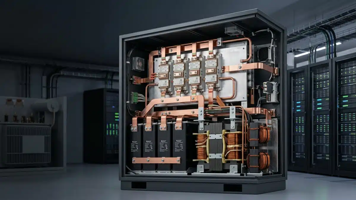
An SST contains one or more DC buses whose capacitors must support stable bus voltage while carrying switching-related ripple current. The capacitor bank may also need to limit transient overvoltage caused by commutation-loop inductance, load steps, fault events, and cable interactions.
Selection should consider:
- Voltage rating and derating: The rating must cover maximum steady-state DC voltage as well as startup, load-rejection, fault, and switching transients. For an 800 V nominal distribution bus, the manufacturer datasheet and the complete system transient analysis should control final voltage selection.
- Ripple-current capability: RMS ripple current, ESR, cooling conditions, and hotspot temperature must be assessed together. A component’s current rating cannot be used independently of its specified frequency, ambient temperature, mounting condition, and lifetime model.
- Inductance and physical layout: Low ESL is particularly important where capacitors form part of the fast commutation loop around SiC switches. Busbar geometry, terminal arrangement, capacitor placement, parallel-current sharing, and connection symmetry can determine whether the installed assembly achieves the expected switching behavior.
- Technology mix: A power stage may use a combination of film capacitors, ceramic capacitors, and bulk-energy capacitors, each serving a different frequency range and energy-storage function. The required combination depends on the converter topology and measured impedance across the relevant frequency spectrum.
For broader selection guidance, see the Passive Components Blog article on DC-link capacitors and their design considerations.
High-frequency magnetics
SSTs use power conversion stages that require magnetic components beyond the conventional utility-frequency transformer. Depending on topology, these may include isolated high-frequency transformers, boost inductors, resonant inductors, differential-mode chokes, common-mode chokes, and auxiliary power magnetics.
Key design checks include:
- Core-loss behavior at the actual switching waveform: Loss depends on switching frequency, flux-density excursion, temperature, waveform shape, DC bias, and material characteristics. A sinusoidal core-loss curve alone may not represent an SST switching waveform.
- Saturation and fault conditions: Inductors and transformer cores must be evaluated for worst-case current, DC offset, startup, inrush, overload, controller malfunction, and fault-clearing intervals.
- Winding loss: Skin effect, proximity effect, conductor selection, interleaving, and cooling influence copper loss at elevated switching frequency.
- Isolation system: Insulation design must address working voltage, repetitive switching stress, surge conditions, partial-discharge risk, creepage, clearance, and the applicable system safety standard. Component qualification alone does not establish final converter-level insulation compliance.
- Parasitic capacitance: Transformer interwinding capacitance and choke capacitance can create common-mode current paths. This can affect conducted and radiated emissions, bearing-current risks in some loads, and the required size of the EMI filter.
Technical highlights
| Published topic | Manufacturer-reported information | Passive-component relevance |
|---|---|---|
| AI data-center distribution | onsemi identifies 800 V HVDC as an emerging architecture for later-this-decade AI infrastructure | Higher DC voltage changes capacitor voltage margin, insulation coordination, protection, and busbar requirements |
| Medium-voltage conversion | The article describes direct conversion from 13.8 kV AC to 800 V DC | SST insulation, magnetic isolation, surge protection, and fault design require system-level validation |
| SST topology | The article states that SST architectures commonly employ cascaded H-bridge topologies | Multiple switching cells may require distributed DC-link energy storage and careful current sharing |
| SiC voltage classes | The article identifies 2.3 kV to 6.5 kV front-end devices and 1.2 kV to 2.3 kV downstream devices | Faster switching and higher voltage increase sensitivity to capacitor ESL, magnetic parasitics, and EMI paths |
| Future high-voltage devices | onsemi discusses 10 kV-class SiC MOSFET development | The announcement does not provide passive-component ratings or qualification requirements for these future device implementations |
Application fit
SST-based systems may be relevant where high-capacity DC loads need a direct connection to medium-voltage distribution infrastructure. onsemi identifies AI data centers, grid modernization, industrial power systems, electrification infrastructure, and EV-charging applications as target areas.
For passive-component suppliers and designers, the most relevant subsystem opportunities include:
- Front-end AC filtering, surge protection, and differential- and common-mode EMI filtering
- Cascaded-cell DC-link capacitor banks and balancing networks
- High-frequency isolated transformer assemblies
- Resonant and boost inductors for DC-DC conversion stages
- Snubber networks and local high-frequency decoupling close to SiC modules
- Output filtering and bus stabilization on 800 V DC distribution links
- Solid-state circuit-breaker and bypass-system support components
- Fast energy-buffer stages for AI load transients
AI racks can create rapid power changes that challenge the upstream power-delivery network. Energy-storage and bus-stabilization approaches are also discussed in the Passive Components Blog article on supercapacitor balancing for AI data-center power systems.
Design-in notes for engineers
- Map capacitor function before selecting technology. Separate bulk-energy storage, DC-link ripple handling, local switching-loop decoupling, resonant-tank capacitance, and EMC functions. A single capacitor technology may not meet all of these requirements.
- Validate at the intended switching conditions. Evaluate capacitance, ESR, dissipation factor, ripple current, self-heating, impedance, and voltage stress at the actual operating frequency and temperature range.
- Treat layout as an electrical component. Measure or model loop inductance, capacitor placement, busbar geometry, parallel paths, and module-to-capacitor connection length. Fast SiC transitions can make the physical interconnect as important as the nominal capacitor value.
- Check magnetic design under non-sinusoidal excitation. Confirm flux density, core loss, winding temperature rise, insulation stress, leakage inductance, and parasitic capacitance using the final control mode and switching waveform.
- Evaluate EMI at system level. Filter insertion loss depends on source and load impedance, grounding, cable configuration, common-mode paths, and the final mechanical assembly. Filter performance measured in a component test fixture does not automatically translate to an installed SST.
- Design for abnormal operation. Review input surge, pre-charge, inrush, startup, load rejection, short circuit, bypass operation, controller fault, and shutdown behavior. These events may impose the highest electrical or thermal stress on capacitors, magnetics, and protection components.
- Confirm insulation coordination early. Working voltage, transient overvoltage, repetitive switching stress, pollution degree, altitude, creepage, clearance, and partial-discharge requirements should be defined before magnetic and capacitor assemblies are frozen.
- Use current documentation for release. onsemi’s article provides architecture and technology positioning, not a complete converter design specification. The current datasheet, application documentation, safety requirements, and system qualification plan must control schematic, layout, and production release.
Further reading
- TDK Ventures Invests in Solid State Transformers Startup
- DC-Link Capacitors – Design Tips
- Murata Publishes Power Delivery Guide for AI Servers
- Bourns Releases Custom SiC AFE/PFC Power Inductor for High-Voltage Designs
Source
This article is based on an onsemi manufacturer article covering SSTs, high-voltage SiC devices, and emerging 800 V HVDC architectures for AI data centers. Engineers should consult current manufacturer datasheets, application documentation, safety requirements, and system-level test results before final component qualification and design release.