








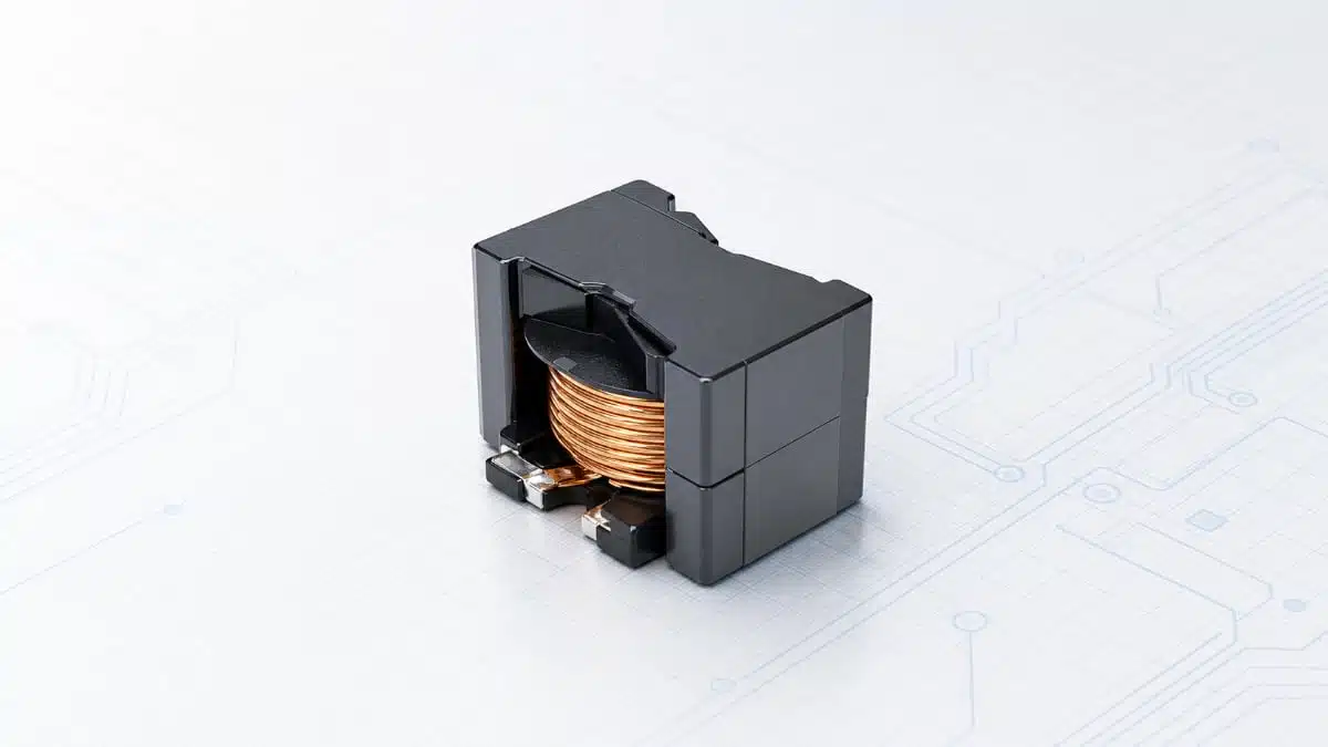
Bourns has released engineering samples of the MAG‑3002410 custom power inductor, originally designed for the Texas Instruments TIDA‑01606 11 kW T‑type inverter and PFC reference design.
This low‑profile, ultra‑low‑DCR power inductor targets bidirectional three‑level SiC active front‑end (AFE) inverter and high‑efficiency PFC stages in demanding high‑voltage systems.
Key features and benefits
- Custom magnetics for TIDA‑01606 architecture – Developed specifically for the Texas Instruments TIDA‑01606 11 kW three‑level T‑type inverter and PFC reference design, making it a strong fit for similar three‑phase SiC AFE topologies and high‑power PFC stages.
- Low‑profile mechanical design – The inductor housing is designed to minimize height, supporting denser power modules, better airflow management, and easier mechanical integration into EV chargers, renewable energy inverters, and industrial power cabinets.
- Ultra‑low DC resistance (DCR) – DCR of approximately 26 mΩ (±25%) helps reduce conduction losses and copper heating, which is particularly important in continuous‑conduction PFC chokes and three‑phase AFE inductors operating at higher average current.
- High inductance with controlled roll‑off – Initial inductance of 160 μH at 0 A with a defined 30% roll‑off at 30 A allows predictable behavior over load, simplifying current ripple estimation and loop stability analysis in design calculations according to the manufacturer datasheet.
- High‑efficiency power conversion – The combination of SiC devices, three‑level topology and low‑loss magnetics supports power conversion efficiencies up to 98.6% in AFE and PFC stages, which is critical for modern EV charging and energy storage infrastructure.
- High‑voltage capability – Hi‑pot rating of 2 kV (5 mA max) provides margin for use in high‑voltage DC buses and galvanically separated stages in central inverters, HVDC links and solid‑state transformers, according to the manufacturer documentation.
- Compliance and customization – RoHS‑compliant construction, with the option to customize the component to match specific application or performance requirements through Bourns engineering support.
Inductor parameters at a glance
The table below summarizes the key electrical parameters of the MAG‑3002410 as specified by the manufacturer.
| Parameter | Typical value |
|---|---|
| Inductance at 0 A | 160 μH, measured at 100 kHz / 1 V |
| Inductance at 30 A | 30% roll‑off from initial value at 100 kHz / 1 V |
| Inductance tolerance | ±10% |
| Saturation current (20% roll‑off) | 30 A |
| DC resistance (DCR) | 26 mΩ, ±25% |
| Hi‑pot test voltage | 2 kV, 5 mA max |
| RoHS status | Compliant to Directive 2015/863 |
Values are based on the manufacturer press release and referenced datasheet information; designers should confirm final ratings in the official datasheet during design‑in.
Typical applications
The MAG‑3002410 targets high‑power, high‑voltage systems where three‑level topologies and SiC devices are increasingly common:
- Central inverters for renewable DC‑to‑AC conversion (solar, fuel cell or hybrid systems).
- DC fast chargers for EV batteries and modular EV charger power stages.
- Energy storage systems interfacing batteries or supercapacitors to AC grids via SiC AFE converters.
- Fuel cell DC‑to‑AC inverters requiring high efficiency and compact magnetics.
- High‑voltage direct current (HVDC) transmission systems and associated power conversion equipment.
- Solid‑state transformers (SSTs) where three‑level structures and high‑frequency magnetics enable compact, high‑efficiency conversion.
In each of these use cases, the combination of low profile and low DCR helps maintain thermal performance while meeting stringent efficiency targets.
Technical highlights
Optimized for three‑level SiC AFE and PFC
The inductor is intended for bidirectional three‑level, three‑phase SiC active front‑end inverter and PFC applications, where higher switching frequency and lower losses enable smaller magnetics and better overall system efficiency. According to the manufacturer, the MAG‑3002410 helps TIDA‑01606‑style systems reach power conversion efficiencies up to 98.6% in the AFE and PFC stages, which reduces cooling requirements and operating costs.
In practical terms, a 160 μH inductor with defined inductance roll‑off characteristics is well suited for use as a phase inductor in a three‑phase AFE or as a high‑power boost/PFC choke on a high‑voltage DC bus. Designers can exploit the inductance curve to balance current ripple, dynamic response and core utilization without resorting to overly conservative margins.
Mechanical and insulation considerations
The low‑profile mechanical design supports space‑constrained rack systems and wall‑mounted EV chargers, where component height can limit enclosure depth or airflow paths. A 2 kV hi‑pot rating and specified test current provide guidance for insulation coordination in systems that may see grid‑level voltages, fault transients or isolation test procedures, according to manufacturer information. Combined with compliance to RoHS Directive 2015/863, the inductor aligns with current industry requirements for environmental and safety standards.
Availability and part numbers
At this stage, the MAG‑3002410 is offered as an engineering sample through selected Bourns distribution partners. The product was validated as part of the Texas Instruments TIDA‑01606 high‑voltage reference design platform and is now being made available to support similar architectures in commercial projects.
Design‑in notes for engineers
- Match topology and current profile – The inductor is tuned for the TIDA‑01606 three‑level SiC AFE/PFC architecture; when re‑using it, verify that your topology (modulation strategy, switching frequency and current waveform) is similar enough to maintain the specified inductance and loss profile according to the official datasheet.
- Use manufacturer curves for inductance vs. current – The press release specifies 160 μH at 0 A and a 30% roll‑off at 30 A; designers should consult full inductance versus current curves to accurately size current ripple, core saturation margin and control loop compensation.
- Account for DCR and thermal design – With DCR around 26 mΩ, conduction losses at high current are moderate but non‑negligible; combine DCR data with estimated RMS current to calculate copper loss and integrate the inductor into your thermal model, including airflow or liquid cooling where applicable.
- Check insulation and creepage/clearance – The 2 kV hi‑pot rating offers guidance on insulation robustness for high‑voltage systems, but final creepage and clearance distances must be validated against IEC/UL standards relevant to your end application and grid voltage level.
- Consider mechanical constraints – The low‑profile format is advantageous for compact systems; verify footprint, mounting scheme and mechanical robustness under vibration or shock in automotive or industrial environments according to the manufacturer datasheet.
- Coordinate with Bourns for customization – Since the components can be customized for specific application and performance needs, it is worth engaging Bourns early in the design cycle if your converter operates at significantly different frequency, voltage or current from TIDA‑01606.
These notes aim to help design engineers leverage a proven custom magnetic developed for a known reference platform while avoiding common pitfalls when transferring such components into new system designs.
Source
This article is based on information provided in the official Bourns new product release for the MAG‑3002410 custom magnetics model and associated technical documentation, with additional context added for design engineers and purchasing professionals.