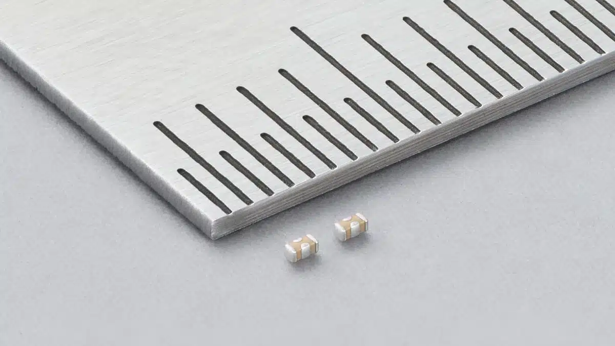
Murata has started mass production of the LLD series, World’s Smallest three-terminal low-ESL multilayer ceramic capacitors in a 0201-inch (0.6 × 0.3 mm) case.
The two new Murata 1 µF Three-Terminal Low-ESL MLCCs are for decoupling the power supply right next to ICs in compact devices, where board space and high-frequency impedance both limit the design.
Key features and benefits
- New case size for a three-terminal MLCC: 0603M/0201 (L 0.6 ± 0.09 mm, W 0.3 ± 0.05 mm, T 0.3 ± 0.05 mm). Murata calls it the world’s smallest three-terminal low-ESL MLCC, based on its own research as of 29 September 2026.
- Smaller footprint: Measured by nominal length × width, the case takes 0.18 mm² versus 0.50 mm² for Murata’s earlier smallest 0402-inch (1.0 × 0.5 mm) three-terminal parts. That is about 64 % less area.
- Two part numbers, both 1 µF ±20 %: LLD033R60G105ME01 (X5R, 4 V DC, −55 °C to +85 °C) and LLD033D80E105ME01 (X6T, 2.5 V DC, −55 °C to +105 °C).
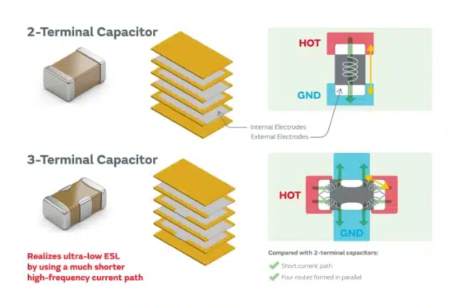
- Low-ESL three-terminal structure: A three-terminal capacitor has four short current paths, which gives lower ESL than a conventional two-terminal chip.
- Scope set by function: The LLD series is for power decoupling. It is not intended as a noise filter. For EMI filtering, the product lineup points to the NFM series.
- Packaging: Paper tape, W8P2. Code D is a 180 mm reel of 15,000 pcs; code J is a 330 mm reel of 50,000 pcs.
Technical highlights
Three-terminal capacitors have more complex internal and external electrodes than two-terminal types, which made them hard to shrink. Murata says it got around this by optimising the electrode design and its manufacturing processes. As a result, a three-terminal low-ESL part now fits a 0201 footprint, where designers could previously only place standard two-terminal MLCCs.
Key technical data
| Parameter | LLD033R60G105ME01 | LLD033D80E105ME01 |
|---|---|---|
| Case size | 0201 (0603M) | 0201 (0603M) |
| Capacitance | 1 µF ±20 % | 1 µF ±20 % |
| Rated voltage | 4 V DC | 2.5 V DC |
| Dielectric (EIA) | X5R | X6T |
| Cap. change vs temp. | −15 % to +15 % | −33 % to +22 % |
| Operating temp. | −55 °C to +85 °C | −55 °C to +105 °C |
| Mounting | Reflow | Reflow |
Capacitance is specified at 1.0 kHz and 0.5 Vrms. The temperature coefficient values are measured with no DC bias. The two parts differ in more than voltage. The X6T part covers 20 °C more at the top of its range, but its capacitance moves much more over temperature. The X5R part has more voltage margin but stops at 85 °C.
Qualification and test data in the specification sheet
The reference sheet tests to JIS C 5101 and IEC 60384 methods. Key results:
- Voltage proof: 250 % of rated voltage for 1–5 s.
- Insulation resistance: more than 50 Ω·F at rated voltage.
- Endurance: 1000 h at maximum operating temperature and 150 % of rated voltage. Capacitance change stays within ±12.5 %, and IR stays above 25 Ω·F.
- Steady-state humidity: 500 h at 40 °C and 90–95 % RH, unbiased. Capacitance change stays within ±12.5 %, and IR stays above 12.5 Ω·F.
- Substrate bending: 1 mm flexure on a 0.8 mm glass-epoxy board, with capacitance change within ±10 %.
- Mechanical and thermal: vibration from 10 Hz to 2000 Hz, 2 N shear, 270 °C soldering-heat resistance, and 10 cycles of rapid temperature change.
The listed application classes are consumer, industrial, automotive infotainment/comfort, and medical GHTF A/B/C (implants excluded).
Typical applications
The main circuit position: power-supply decoupling for high-speed ICs. This matches the LLD series scope and the low-ESL construction.
- Point-of-load decoupling near processors and SoCs: Low ESL and a 1 µF value suit these parts to the high-frequency part of a power distribution network. There, fast load-current changes would otherwise show up as supply-voltage fluctuation.
- Low-voltage core and I/O rails: The 2.5 V and 4 V DC ratings limit use to low-voltage rails. The limit applies to the peak voltage, including ripple and transients.
- Hotter spots in the device: The 105 °C X6T part covers local hot spots better than the 85 °C X5R part.
Smartphones and wearables are among the target devices for these capacitors. This fits the consumer-equipment application class in the specification sheet.
Application fit
| Application | Supporting ratings | Check first |
|---|---|---|
| SoC core-rail decoupling | 1 µF, low ESL, 2.5 V DC | DC bias, peak voltage |
| I/O or memory rails | 1 µF, 4 V DC | Rail max. + ripple |
| Hot-spot PDN positions | X6T, 105 °C | Capacitance vs temp. |
| Infotainment electronics | Listed application class | No AEC-Q200 stated |
Design-in notes for engineers
- Rated voltage is an absolute limit. Under DC plus AC, the zero-to-peak voltage must stay at or below the rated DC voltage. Surges, ESD, and pulse voltages must also stay below it. With 2.5 V and 4 V ratings, rail tolerance and load-step overshoot leave little margin.
- Plan for DC-bias loss. X5R and X6T are high-permittivity Class II dielectrics, so capacitance drops with applied DC voltage, even below the rated voltage. See the article on DC bias in Class II MLCCs. The effective capacitance at the real rail voltage and temperature matters more than the 1 µF nominal value.
- Watch self-heating. Under AC or pulse load, self-heating of the capacitor body should stay below 20 °C, measured at 25 °C ambient. The surface temperature, including self-heating, must not exceed the maximum operating temperature.
- Ground connection sets the real ESL. For chip three-terminal capacitors in general, Murata’s guidance is to keep the ground-side pattern thick and short and mount the part close to the ground layer. Via length and placement also matter. Mounted inductance, not part ESL alone, sets the high-frequency performance. It should be checked with the final stack-up.
- Land pattern and board stress. The sheet gives LLD03 reflow land dimensions but says they must be confirmed on the real board. When moving to a smaller case, trace width, trace direction, and copper thickness should be reviewed along with the land size, because a land-size change alone raises the risk of cracking.
- Acoustic noise. High-permittivity MLCCs can vibrate under AC or pulse voltage and make audible noise. This is worth checking in wearables and handsets with fast load transients.
- Not a filter part. Where the job is EMI filtering instead of decoupling, the lineup points to the NFM series.
Before schematic freeze, get ESL, impedance, and DC-bias data for the exact part number. Run the PDN simulation with the mounted geometry. Then confirm performance on the actual board under worst-case voltage and temperature. The component data do not replace system-level validation.
Further reading
- MLCC DC BIAS and AGEING Capacitance Loss Explained
- Temperature, Bias and Ageing Impact to Capacitance Stability of MLCC Ceramic Capacitors
- Low Inductance Ceramic Capacitors for High-Speed Decoupling
Source
This article is based on the Murata press release and official Murata product documentation, including the product pages and reference specification sheets for both part numbers. Engineers should check the current Murata datasheet, approval sheet, and characterisation data before final qualification and design release.
References
- Murata Manufacturing, “Murata Begins Mass Production of World’s Smallest 0201-inch Size Three-Terminal Low-ESL MLCCs,” press release, 30 September 2026.
- Murata, LLD033R60G105ME01# product page.
- Murata, LLD033D80E105ME01# product page.
- Murata, LLD033R60G105ME01 reference specification sheet, rev. 01A (as of 29 September 2026).
- Murata, LLD033D80E105ME01 reference specification sheet, rev. 01A (as of 29 September 2026).
- Murata, LLD Series lineup page.
- Murata, “Basics of Noise Countermeasures [Lesson 11]: Notes on the Use of Chip 3-Terminal Capacitors.”