











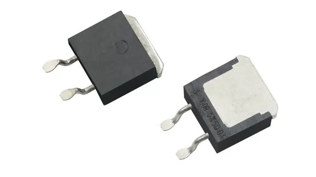
Vishay has introduced the Sfernice D2TO35S, a thick-film surface-mount power resistor in a TO-263 (D2PAK) package with a top-side cooling interface.
The new Vishay power resistor variant moves the principal heat-removal path to a heatsink above the package, addressing applications in which PCB copper alone cannot remove the required continuous dissipation.
Key features and benefits
- 35 W rated dissipation at a 25 °C top-side temperature, provided the specified top-side thermal path is implemented.
- Top-side cooling through the TO-263 package, allowing the PCB to carry electrical connections while the heatsink removes most of the heat.
- AEC-Q200 qualification supports use in automotive-grade passive-component supply chains; it is a component stress-test qualification, not vehicle-level approval.
- Non-inductive thick-film construction is relevant where resistance is used in circuits with fast current transitions.
- RoHS-compliant reflow capability includes a 270 °C / 10 s soldering limit.
- Vishay positions the D2TO35S for designs seeking higher dissipation from a compact surface-mount resistor footprint. The attainable power in the finished product remains determined by the complete heatsink, interface material, mounting force, ambient temperature, airflow, and derating conditions.
Technical highlights
The release identifies only one series and package configuration: D2TO35S, a top-side-cooled TO-263 (D2PAK) resistor. No individual ordering part numbers, sub-families, alternative case sizes, qualification reports, pulse-load curves, SPICE models, or product-change notices were publicly identified in the reviewed documentation.
| Parameter | Value | Selection relevance |
|---|---|---|
| Technology | Thick film | Surface-mount power resistor |
| Package | TO-263 / D2PAK | Top-side cooling interface |
| Rated power | 35 W | At 25 °C top-side temperature |
| Resistance range | 4.7 Ω to 550 kΩ | Covers current sense through damping roles |
| Tolerance | Down to ±1% | Resistance-set accuracy |
| TCR | Down to ±150 ppm/°C | Resistance shift with temperature |
| Operating range | −55 °C to +175 °C | Element-temperature limit |
| Thermal resistance | 4.28 °C/W | Resistor element to case/top-side path |
| Qualification | AEC-Q200 | Passive-component stress qualification |
| Reflow limit | 270 °C / 10 s | Assembly-process constraint |
The announcement gives a resistance range of 4.7 Ω to 550 kΩ. The current thermal-management application note instead gives 4.7 Ω to 700 kΩ for D2TO35S. The press-release figure is used here because the current datasheet itself could not be opened through the public document interface; engineers should confirm the selectable resistance range and associated electrical limits in the current D2TO35S datasheet before release.
The 35 W figure is not a general PCB-mounted rating. It applies with the top side held at 25 °C. The application note reports a 15 W laboratory result on a 39 mm × 30 mm × 1.6 mm double-sided FR4 HTG board with 70 µm copper, an 80 mm × 48 mm × 73 mm air-cooled heatsink, and thermal grease. That result is a specific evaluated assembly, not a universal installed-board dissipation rating.
Typical applications
The available documentation supports power-resistor positions in systems where an engineered heatsink can maintain the required top-side temperature.
| Circuit position | Supporting published ratings | Practical relevance |
|---|---|---|
| Power dissipation resistor | 35 W at 25 °C top side | Requires heatsink path |
| Current limiting or braking path | 4.7 Ω to 550 kΩ range | Final pulse rating must be checked |
| Snubber or damping resistor | Non-inductive thick-film design | Check voltage and pulse energy |
| Automotive power electronics | AEC-Q200 qualification, −55 °C to +175 °C | Validate full system conditions |
| Compact industrial power stage | TO-263 top-side cooling | Preserves PCB area for routing |
The product page names automotive use, while the release also refers to industrial, computing, consumer, telecommunications, military, aerospace, and medical markets in Vishay’s general corporate description. Those broader markets are not product-specific application endorsements and are therefore not treated as validated D2TO35S target applications here.
For fast-switching paths, the non-inductive construction can be useful where parasitic inductance would alter transient response. This does not establish pulse-energy capability by itself: no D2TO35S-specific pulse-load graph or surge-energy rating was located in the reviewed public documentation. Snubber, clamp, precharge, inrush, and braking applications must therefore be checked against the current datasheet and system waveform.
Design-in notes for engineers
- Treat the 35 W rating as a thermal-system rating, not solely as a resistor rating. The specified condition is a 25 °C top-side temperature.
- Use the resistor’s 4.28 °C/W thermal resistance together with the thermal interface, heatsink-to-ambient resistance, enclosure temperature, airflow, and nearby dissipating parts.
- The thermal-management application note identifies the PCB as a frequent limiting element in conventional surface-mount power-resistor installations. The top-side heatsink changes the dominant heat path, but solder-joint quality and local PCB temperature still require validation.
- Follow the D2TO35S mounting guidance in the current datasheet. The reviewed application note explicitly directs users to the datasheet for D2TO35S mounting recommendations rather than publishing the detail in the note.
- Validate thermal interface material selection, heatsink flatness, contact pressure, assembly tolerances, vibration performance, and the maximum steady-state resistor-element temperature.
- Confirm resistance tolerance and TCR at the actual resistance value selected. “Down to” ±1% and ±150 ppm/°C do not establish that every available resistance value carries those limits.
- Confirm voltage stress, repetitive pulse energy, fault conditions, creepage and clearance, and PCB temperature under worst-case line, load, ambient, and cooling conditions before schematic and layout release.
- Use a controlled reflow profile compatible with the 270 °C / 10 s limit. The application note refers to JEDEC J-STD-020C profile guidance, but a D2TO35S-specific moisture-sensitivity classification was not identified in the reviewed public documents.
- The resistor thermal-resistance and temperature-coefficient guide is useful for interpreting thermal resistance, while the resistor pulse-load and derating design guide covers the distinction between nameplate dissipation and installed operating conditions.
Further reading
- What Is a Resistor? Types, Ratings and Selection
- Resistors Pulse Load and Derating Design Guide
- Resistors Resistivity, Thermal Resistance and Temperature Coefficient
- Thick-Film Chip Resistors: Construction, Properties, Selection and Design
Source
This article is based on the Vishay D2TO35S press release, product information page, and official thermal-management application note. Engineers should consult the current D2TO35S datasheet and associated manufacturer documentation for final part selection, mounting design, qualification review, and production release.
References
- Vishay Intertechnology Releases New Top-Side Cooling Mount Thick Film Power Resistor in Compact TO-263 (D2PAK) Package
- Vishay D2TO35S Product Information: Surface Mount Power Resistor, Thick Film Technology, TO-263 Top Side Cooling
- Vishay Application Note 52027: Thermal Management on SMD Thick Film Resistors












