











Passive Components Blog
No Result
View All Result
  • Home
  • NewsFilter
    • All
    • Aerospace & Defence
    • Antenna
    • Applications
    • Automotive
    • Capacitors
    • Circuit Protection Devices
    • electro-mechanical news
    • Filters
    • Fuses
    • Inductors
    • Industrial
    • Integrated Passives
    • inter-connect news
    • Market & Supply Chain
    • Market Insights
    • Medical
    • Modelling and Simulation
    • New Materials & Supply
    • New Technologies
    • Non-linear Passives
    • Oscillators
    • Passive Sensors News
    • Resistors
    • RF & Microwave
    • Telecommunication
    • Weekly Digest

    LeanBOM: Practical Cross‑Technology Capacitor Search by Real Working Conditions

    In the Age of AI, Every Watt Counts: Implications for Components

    Stackpole Extends Resistance Range of 2512 High‑Power Current Sense Resistors

    Wk 27 Electronics Supply Chain Digest

    Littelfuse Announced TVS Diodes for 48 V Automotive Systems

    Spectrum Controls Joins Modelithics Program to Offer High‑Fidelity RF Models for Resistors, Attenuators and Terminations

    RF Filters and Passive Components Enabling the 7 Missile RF Subsystems

    Ferrite versus Nanocrystalline Power Inductor Cores: Turns, Gap and Size

    YAGEO Presents NANOMET Soft Magnetic Cores for High‑Density Power Conversion

    Trending Tags

    • Ripple Current
    • RF
    • Leakage Current
    • Tantalum vs Ceramic
    • Snubber
    • Low ESR
    • Feedthrough
    • Derating
    • Dielectric Constant
    • New Products
    • Market Reports
  • VideoFilter
    • All
    • Antenna videos
    • Capacitor videos
    • Circuit Protection Video
    • Filter videos
    • Fuse videos
    • Inductor videos
    • Inter-Connect Video
    • Non-linear passives videos
    • Oscillator videos
    • Passive sensors videos
    • Resistor videos

    Ferrite versus Nanocrystalline Power Inductor Cores: Turns, Gap and Size

    KYOCERA AVX Presents Antenna Integrator Studio Tutorial for Antenna Placement and RF Design

    Power Design Simulation Tools for Faster Inductor Selection and Loss Optimization

    EMC‑Compliant PCB and Connector Design Guidelines

    Why Isolated DC/DC Power Supplies Fail Late, Würth Elektronik Podcast

    Designing 800 V DC EMC Filters: Calculation, Simulation and Measurement

    Current Sense Transformer Datasheet and Design‑in Guide

    Designing a USB Type‑C Flyback Planar Transformer with Frenetic’s Planar Tool

    Magnetics Design in High‑Frequency GaN Converters

    Trending Tags

    • Capacitors explained
    • Inductors explained
    • Resistors explained
    • Filters explained
    • Application Video Guidelines
    • EMC
    • New Products
    • Ripple Current
    • Simulation
    • Tantalum vs Ceramic
  • Knowledge Blog
  • Dossiers
    • AI Hardware Dossier
    • Power Converter Dossier
    • Automotive Dossier
    • Capacitor Dossier
    • Resistor Dossier
    • Inductor Dossier
    • Circuit Protection Dossier
  • Suppliers
    • Who is Who
  • PCNS
    • PCNS 2025
    • PCNS 2023
    • PCNS 2021
    • PCNS 2019
    • PCNS 2017
  • Events
  • Home
  • NewsFilter
    • All
    • Aerospace & Defence
    • Antenna
    • Applications
    • Automotive
    • Capacitors
    • Circuit Protection Devices
    • electro-mechanical news
    • Filters
    • Fuses
    • Inductors
    • Industrial
    • Integrated Passives
    • inter-connect news
    • Market & Supply Chain
    • Market Insights
    • Medical
    • Modelling and Simulation
    • New Materials & Supply
    • New Technologies
    • Non-linear Passives
    • Oscillators
    • Passive Sensors News
    • Resistors
    • RF & Microwave
    • Telecommunication
    • Weekly Digest

    LeanBOM: Practical Cross‑Technology Capacitor Search by Real Working Conditions

    In the Age of AI, Every Watt Counts: Implications for Components

    Stackpole Extends Resistance Range of 2512 High‑Power Current Sense Resistors

    Wk 27 Electronics Supply Chain Digest

    Littelfuse Announced TVS Diodes for 48 V Automotive Systems

    Spectrum Controls Joins Modelithics Program to Offer High‑Fidelity RF Models for Resistors, Attenuators and Terminations

    RF Filters and Passive Components Enabling the 7 Missile RF Subsystems

    Ferrite versus Nanocrystalline Power Inductor Cores: Turns, Gap and Size

    YAGEO Presents NANOMET Soft Magnetic Cores for High‑Density Power Conversion

    Trending Tags

    • Ripple Current
    • RF
    • Leakage Current
    • Tantalum vs Ceramic
    • Snubber
    • Low ESR
    • Feedthrough
    • Derating
    • Dielectric Constant
    • New Products
    • Market Reports
  • VideoFilter
    • All
    • Antenna videos
    • Capacitor videos
    • Circuit Protection Video
    • Filter videos
    • Fuse videos
    • Inductor videos
    • Inter-Connect Video
    • Non-linear passives videos
    • Oscillator videos
    • Passive sensors videos
    • Resistor videos

    Ferrite versus Nanocrystalline Power Inductor Cores: Turns, Gap and Size

    KYOCERA AVX Presents Antenna Integrator Studio Tutorial for Antenna Placement and RF Design

    Power Design Simulation Tools for Faster Inductor Selection and Loss Optimization

    EMC‑Compliant PCB and Connector Design Guidelines

    Why Isolated DC/DC Power Supplies Fail Late, Würth Elektronik Podcast

    Designing 800 V DC EMC Filters: Calculation, Simulation and Measurement

    Current Sense Transformer Datasheet and Design‑in Guide

    Designing a USB Type‑C Flyback Planar Transformer with Frenetic’s Planar Tool

    Magnetics Design in High‑Frequency GaN Converters

    Trending Tags

    • Capacitors explained
    • Inductors explained
    • Resistors explained
    • Filters explained
    • Application Video Guidelines
    • EMC
    • New Products
    • Ripple Current
    • Simulation
    • Tantalum vs Ceramic
  • Knowledge Blog
  • Dossiers
    • AI Hardware Dossier
    • Power Converter Dossier
    • Automotive Dossier
    • Capacitor Dossier
    • Resistor Dossier
    • Inductor Dossier
    • Circuit Protection Dossier
  • Suppliers
    • Who is Who
  • PCNS
    • PCNS 2025
    • PCNS 2023
    • PCNS 2021
    • PCNS 2019
    • PCNS 2017
  • Events
No Result
View All Result
Passive Components Blog
No Result
View All Result

High‑Speed Supercapacitor Balancing for AI Data Center Power Systems

23.6.2026
Reading Time: 6 mins read
A A

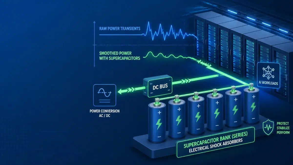
The rapid adoption of artificial intelligence is reshaping the electrical profile of modern data centers. Unlike legacy compute workloads, AI accelerators generate short, aggressive bursts of power demand that last from a few hundred milliseconds up to a couple of seconds.These repetitive transients can significantly reduce power quality and accelerate the degradation of power conversion and energy storage components throughout the power chain.

To mitigate these effects, many operators are introducing supercapacitor banks as fast energy buffers. Acting as electrical “shock absorbers,” supercapacitors help to smooth rapid and cyclical load profiles and complement existing generation, distribution, and battery energy storage assets. However, when deployed at high voltage and large scale, supercapacitors introduce their own challenge: maintaining cell‑to‑cell voltage balance under highly dynamic load conditions.

RelatedPosts

Capacitech C-Link Supercapacitors for AI Data Center Voltage Spikes Mitigation

Cable Supercapacitors in Microgrids and Renewable Applications

Capacitech PowerLink: High Power Cable Supercapacitor Energy Storage for Space Constrained Applications

Supercapacitor Banks and the Balancing Challenge

To reach the DC bus voltages used in modern data centers, hundreds or thousands of individual supercapacitor cells are typically connected in series, and often in series‑parallel arrangements. As with battery packs, these multi‑cell structures are subject to cell‑to‑cell variations caused by manufacturing tolerances. Supercapacitor cells can differ in leakage current, equivalent series resistance (ESR), and capacitance, with typical capacitance tolerances on the order of −10% to +20%.

Because capacitance directly affects how quickly the voltage across a cell changes during charge and discharge, these parameter spreads naturally result in voltage imbalance when the bank is cycled. Under AI‑like repetitive pulses, even small differences can accumulate into a compounding feedback loop: certain cells see disproportionate electrical and thermal stress, experience overvoltage earlier, age faster, and may eventually be pushed toward rupture or venting if the imbalance is not controlled.

This behavior mirrors what is well known from battery energy storage systems, where battery management systems (BMS) are used to monitor and balance cells. High‑energy supercapacitor banks require an equivalent level of supervision and balancing, but they must operate effectively on the much shorter time scales associated with AI‑driven load dynamics.

Traditional Balancing Approaches and Their Limits

Three common supercapacitor balancing method strategies are used today to manage voltage imbalance in supercapacitor banks. While effective in slower or less dynamic systems, each has significant limitations when applied to AI data center workloads with frequent and steep power transients.

  • Passive resistor balancing
    In passive schemes, fixed resistors are placed in parallel with each cell to bleed off excess charge from higher‑voltage cells. This method is simple, low‑cost, and easy to implement, but balancing currents are typically in the milliamp range and thus limited to sub‑watt power levels. At these current levels, correction times are long compared to AI workload repetition rates, so imbalance can grow between pulses even while the balancing network is active.
  • Conventional active balancing (op‑amp or MOSFET based)
    Active topologies based on operational amplifiers or MOSFET switches transfer charge more selectively from higher‑voltage to lower‑voltage cells. These systems are generally designed to address slow, leakage‑driven drift and operate at low currents that are adequate for long time‑scale equalization. Under fast, transient‑heavy workloads, however, they lack both the current capability and the response speed required to correct imbalances within the time between load pulses.
  • System oversizing
    A non‑electronic “solution” sometimes used is to oversize the system: adding extra series cells to create a larger voltage safety margin, or adding parallel strings to dilute the effect of parameter variation. While this can reduce the risk of individual cells reaching overvoltage, it increases component count, volume, and cost, and it does not solve the root cause of imbalance. In a space‑ and cost‑constrained data center environment, such oversizing directly competes with compute density.

In all three cases, the core limitation is the characteristic time needed to bring a given cell‑to‑cell voltage difference back within a safe window. If that time is longer than the interval between AI load pulses, then imbalance tends to accumulate rather than being actively bounded.

Concept of High‑Speed Active Balancing

To support AI‑class load profiles, the balancing system must act on the same time scale as the disturbance it is trying to correct. In practice, this means that cell‑to‑cell voltage imbalances should be detected and substantially corrected before the next high‑power pulse arrives.

High‑speed active balancing topologies are designed with this constraint in mind. They continuously monitor the voltage of each cell and can apply corrective charge transfer at amp‑level currents instead of milliamp levels. By raising balancing currents by orders of magnitude, the time required to reduce a given voltage difference is reduced from tens of seconds to sub‑second territory, depending on the specific implementation details and operating conditions.

C-Link supercapacitor cable company Capacitech published implementation example that reports the time needed to correct a 0.014 V cell‑to‑cell imbalance using different approaches:

  • High‑speed active topology: less than 1 second
  • Conventional op‑amp‑based active balancing: more than 13 seconds
  • Conventional MOSFET‑based active balancing: more than 33 seconds
  • Passive resistor balancing: more than 59 seconds

While these numbers are specific to a particular system design, they illustrate the order‑of‑magnitude differences in correction speed between milliamp‑level and amp‑level balancing strategies. Faster correction effectively flattens the growth of cell voltage divergence over many load cycles, helping to keep all cells within their specified voltage range even under aggressive and repetitive load transients.

Design Implications for AI Data Center Power

For designers of AI‑oriented data center power systems, the choice of balancing strategy has direct implications for safety margins, component stress, and overall system efficiency. If balancing cannot keep up with the load dynamics, larger design margins and oversizing become necessary to protect the weakest cells, which increases cost and volume and can reduce energy density.

Implementing high‑speed active balancing allows designers to reduce the reliance on brute‑force oversizing while maintaining or improving reliability. By limiting cell‑to‑cell overvoltage excursions, high‑speed balancing can help extend the lifetime of supercapacitor banks and associated power electronics. At system level, the result is a power architecture that is better aligned with the short‑duration, high‑repetition workloads characteristic of AI accelerators, without resorting to excessive component count or conservative derating alone.

As AI data centers continue to scale in power density, high‑voltage supercapacitor banks combined with appropriately fast balancing architectures are likely to become a key building block in the overall power delivery strategy. Future work in this area will include long‑term reliability data, standardization efforts around design and safety requirements, and integration of supercapacitor management functions with existing battery and power management systems.

Reference

This post is based on insights and example data from a technical article Why High-Speed Balancing is Critical for Data Centers originally published by Capacitech Energy on high‑speed balancing for data centers.


Related

Recent Posts

LeanBOM: Practical Cross‑Technology Capacitor Search by Real Working Conditions

13.7.2026
3

In the Age of AI, Every Watt Counts: Implications for Components

13.7.2026
4

RF Filters and Passive Components Enabling the 7 Missile RF Subsystems

9.7.2026
42

From DCL to SSC: Bridging Electrical Symptoms and Structural Indicators in Tantalum Capacitors

7.7.2026
54

High-Q RF & Microwave MLCCs: A Cross-Vendor Benchmark

2.7.2026
80

TAIYO YUDEN Introduced Hybrid Aluminum Capacitors for 48V Automotive Power Supplies

2.7.2026
73

YAGEO Announces July 2026 Capacitor Price Increase

1.7.2026
713

Enabling the 800 V AI Server Era: How C0G High-Voltage MLCC Supports Next-Generation Power Architectures

1.7.2026
159

MLCCs in the Age of AI: Q2 2026 Market Tightness

30.6.2026
453

Upcoming Events

Jul 14
16:00 - 17:00 CEST

EMC Design Essentials: Mastering Varistors and Common Mode Chokes

Jul 21
16:00 - 17:00 CEST

Safety by design: X and Y Interference suppression capacitors for power line filters

Jul 28
8:00 - 11:00 CEST

Post Procurement Testing of EEE Components for LEO Space Applications

View Calendar

Popular Posts

  • Boost Converter Design and Calculation

    0 shares
    Share 0 Tweet 0
  • Buck Converter Design and Calculation

    0 shares
    Share 0 Tweet 0
  • Flyback Converter Design and Calculation

    0 shares
    Share 0 Tweet 0
  • LLC Resonant Converter Design and Calculation

    0 shares
    Share 0 Tweet 0
  • YAGEO Announces July 2026 Capacitor Price Increase

    0 shares
    Share 0 Tweet 0
  • MLCC and Ceramic Capacitors

    0 shares
    Share 0 Tweet 0
  • Earthing Systems and IEC Classification Explained

    0 shares
    Share 0 Tweet 0
  • Nvidia Vera Rubin: Why One AI Rack Needs So Many More MLCC Capacitors

    0 shares
    Share 0 Tweet 0
  • MLCCs in the Age of AI: Q2 2026 Market Tightness

    0 shares
    Share 0 Tweet 0
  • Dual Active Bridge (DAB) Topology

    0 shares
    Share 0 Tweet 0

Newsletter Subscription


Passive Components Blog

© EPCI - Leading Passive Components Educational and Information Site

  • Home
  • Privacy Policy
  • EPCI Membership & Advertisement
  • About

No Result
View All Result
  • Home
  • Knowledge Blog
  • Dossiers
  • PCNS

© EPCI - Leading Passive Components Educational and Information Site

This website uses cookies. By continuing to use this website you are giving consent to cookies being used. Visit our Privacy and Cookie Policy.
Go to mobile version










