Passive Components Blog
No Result
View All Result
  • Home
  • NewsFilter
    • All
    • Aerospace & Defence
    • Antenna
    • Applications
    • Automotive
    • Capacitors
    • Circuit Protection Devices
    • electro-mechanical news
    • Filters
    • Fuses
    • Inductors
    • Industrial
    • Integrated Passives
    • inter-connect news
    • Market & Supply Chain
    • Market Insights
    • Medical
    • Modelling and Simulation
    • New Materials & Supply
    • New Technologies
    • Non-linear Passives
    • Oscillators
    • Passive Sensors News
    • Resistors
    • RF & Microwave
    • Telecommunication
    • Weekly Digest

    Bourns Releases High Inductance Common Mode Choke

    Vishay Releases Automotive TO-220 Case 50W Thick Film Power Resistor

    High Energy Density Polymer Film Capacitors via Molecular and Interfacial Design

    Bourns Releases High Clearance and Creepage 1500VDC Power Transformer

    KYOCERA AVX Expands Stacked MLCC Capacitors Offering

    Murata and QuantumScape Joint Development for Solid Batteries Ceramic Separators

    YAGEO Unveils Compact 3.6kW LLC Transformer for OBC EV Charging

    Over-Voltage Protection Clippers, Clampers, Snubbers, DC Restorers

    KYOCERA Releases Shielded Board-to-Board Connectors for Reliable EMI Protection

    Trending Tags

    • Ripple Current
    • RF
    • Leakage Current
    • Tantalum vs Ceramic
    • Snubber
    • Low ESR
    • Feedthrough
    • Derating
    • Dielectric Constant
    • New Products
    • Market Reports
  • VideoFilter
    • All
    • Antenna videos
    • Capacitor videos
    • Circuit Protection Video
    • Filter videos
    • Fuse videos
    • Inductor videos
    • Inter-Connect Video
    • Non-linear passives videos
    • Oscillator videos
    • Passive sensors videos
    • Resistor videos

    Connector PCB Design Challenges

    Efficient Power Converters: Duty Cycle vs Conduction Losses

    Ripple Steering in Coupled Inductors: SEPIC Case

    SEPIC Converter with Coupled and Uncoupled Inductors

    Coupled Inductors in SEPIC versus Flyback Converters

    Non-Linear MLCC Class II Capacitor Measurements Challenges

    Percolation Phenomenon and Reliability of Molded Power Inductors in DC/DC converters

    Root Causes and Effects of DC Bias and AC in Ceramic Capacitors

    How to Calculate the Output Capacitor for a Switching Power Supply

    Trending Tags

    • Capacitors explained
    • Inductors explained
    • Resistors explained
    • Filters explained
    • Application Video Guidelines
    • EMC
    • New Products
    • Ripple Current
    • Simulation
    • Tantalum vs Ceramic
  • Knowledge Blog
  • Suppliers
    • Who is Who
  • PCNS
    • PCNS 2025
    • PCNS 2023
    • PCNS 2021
    • PCNS 2019
    • PCNS 2017
  • Events
No Result
View All Result
Passive Components Blog
No Result
View All Result

Temperature, Bias and Ageing Impact to Capacitance Stability of MLCC Ceramic Capacitors

24.1.2023
Reading Time: 6 mins read
A A

The blog article written by Robert Lu, KYOCERA-AVX Corporation explains impact of several factors such as temperature, applied DC/AC bias voltage, and age to capacitance stability of MLCC ceramic capacitors.

The multi-layer ceramic capacitor (MLCC) is one of the most common capacitor varieties found in electronic design. It offers a wide range of bulk capacitance and voltage tolerance in numerous form factors at relatively low cost. While these devices have become commonplace in the designers’ tool chest, they exhibit some often overlooked peculiarities.

RelatedPosts

KYOCERA AVX Expands Stacked MLCC Capacitors Offering

KYOCERA Releases Shielded Board-to-Board Connectors for Reliable EMI Protection

Kyocera Launches New SAW Filter for GNSS 1.6GHz Satellite Communications

Of primary concern is the sensitivity of effective capacitance to several environmental factors, including temperature, applied bias voltage, and age. If these factors are unaccounted for, the risk of product failure becomes very real, especially in manufacturing variability and overall tolerance stack-up.

MLCC Temperature Considerations

MLCC’s are typically divided into two classes based on the type of ceramic material used for the dielectric. Class I capacitors are the most robust with the fewest sensitivities and are usually built from TiO2. A three-letter EIA code is used to classify the temperature coefficient (TC) in ppm per degree Celsius, a multiplier, and a tolerance. Class I capacitors are often listed as C0G, which is the lowest of all temperature sensitivities, implying a -55°C to +125°C temperature range with a capacitance change of ±30ppm/°C and total capacitance varying less than ±0.3%.

Class II capacitors are typically constructed from BaTiO3 dielectrics and provide a much wider range of bulk capacitance at the expense of higher temperature sensitivity. The commonly used Class II devices are X7R, Y5V, Z5U. Table 1 presents the EIA codes and corresponding values for temperature coefficient and capacity range.

Using Table 1, a few examples are shown below:

  • -55 to +125 degrees with a capacitance change of ±15% EIA code is X7R
  • -55 to +85 degrees with a capacitance change of ±15% EIA code is X5R
  • -30 to +85 degrees with a capacitance change of +22%, -82% EIA code is Y5V
Table 1. Ceramic class dielectric EIA code
Figure 1 – Change in MLCC capacitance versus temperature for different EIA codes

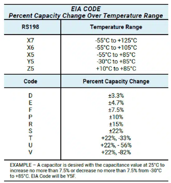
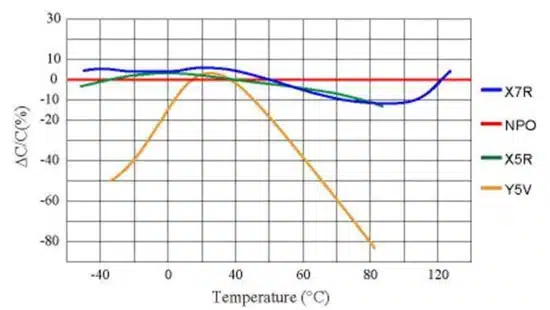
Figure 1 depicts the change in capacitance across the entire temperature range for several different EIA coded MLCC’s. Knowing the environmental conditions in which a capacitor operates and understanding the design’s tolerable variation can be critical to proper functionality. For example, in a high-temperature application, picking a low-cost Y5V device instead of a more appropriate X7R device would all but guarantee its failure.

DC BIAS Voltage Impact to MLCC Capacitors

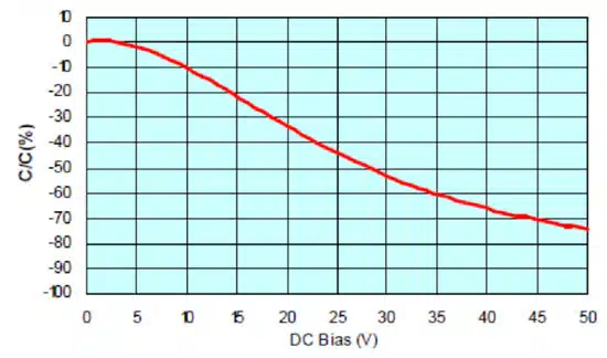
Another inherent sensitivity of MLCC capacitors is the change in bulk capacitance with applied DC bias voltage. For example, as shown in Figure 2, the larger the applied DC voltage, the smaller effective capacitance. The capacitance in this example drops by approximately 45% at 25V, which is only half of the device’s 50V rating.

The origin of this phenomenon is the crystal structure of the ceramic dielectric. With no DC voltage applied, no electric field is present, and the crystal dipoles will arrange themselves randomly throughout the device. This scenario is referred to as spontaneous polarization and results in a high dielectric constant and, in turn, yields high capacitance.

Figure 2 – Change in capacitance versus applied DC voltage for an automotive X7R 50V MLCC
Figure 3 – Crystal polarization without (top) and with (bottom) applied DC bias voltage

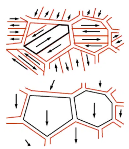
As a low DC voltage is applied, the electric field causes some of the dipoles to align in parallel, as shown in Figure 3. This alignment of dipoles with the electric field decreases capacitance. As more DC voltage is applied, more dipoles will begin to align, and the capacitance continually degrades. Once the rated voltage is reached, capacitance levels can drop by as much as 70% from their nominal value. Class II devices, in particular, suffer from this due to their BaTiO3 construction.

Just as in the case of temperature sensitivity, being aware of the dependence on DC bias voltage can greatly influence a design. If an MLCC is being used to filter a small AC signal with minimal DC component, various MLCC options may be suitable. If, instead, the design is filtering the ripple from a high voltage DC regulator, the MLCC may not be the best choice.

The key factor of DC bias dependence is the thickness of the dielectric. As the dielectric gets thicker, the electric field intensity is weakened, and the capacitance reduction is minimal. Therefore, to minimize the DC bias effect, a designer can apply the following techniques:

  • Choose a larger case size
  • Choose higher rated voltage
  • Choose a better dielectric
  • Put multiple devices in parallel

MLCC Ageing

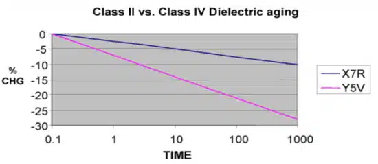
The dielectric materials used in higher class MLCC’s to achieve high capacitance suffer from an inherent aging process. The crystal lattice of these materials has built-in strain energy that gives rise to a permanent electric dipole. Over time, this strain relaxes, and the capacitance slowly degrades.

Figure 4 shows an example of an X7R and Y5V device over 1000 hours of aging. While this aging process can be reversed by raising the device’s temperature above 120C, the designer must simply include the aging effect into the lifetime calculations of the product.

Figure 4 – X7R vs Y5V MLCC ceramic dielectric age degradation of capacitance

Conclusion

While MLCC’s are invaluable devices in modern electronic design, their limitations must be understood. Unlike other capacitor technologies, the designer needs to be intimately familiar with the intended application’s temperature, DC bias, and aging requirements. Only then can the proper dielectric material, case size, and circuit topology be decided.

Further read:

  • High CV MLCC DC BIAS and AGEING Capacitance Loss Explained

Related

Source: KYOCERA AVX

Recent Posts

High Energy Density Polymer Film Capacitors via Molecular and Interfacial Design

15.10.2025
8

KYOCERA AVX Expands Stacked MLCC Capacitors Offering

14.10.2025
16

KYOCERA Releases Shielded Board-to-Board Connectors for Reliable EMI Protection

13.10.2025
21

Silicon Capacitors Market: Shaping the Foundation for Next-Gen Miniaturization Electronics

10.10.2025
40

Enhancing Energy Density in Nanocomposite Dielectric Capacitors

9.10.2025
32

Advances in the Environmental Performance of Polymer Capacitors

8.10.2025
62

Vishay Releases DLA Tantalum Polymer Capacitors for Military and Aerospace

8.10.2025
27

Paumanok Releases Capacitor Foils Market Report 2025-2030

7.10.2025
28

Modelithics Welcomes CapV as a Sponsoring MVP

7.10.2025
4

Benefits of Tantalum Powder Stress–Strain Curve Evaluation vs Conventional Wet Test

3.10.2025
26

Upcoming Events

Oct 17
12:00 - 14:00 EDT

External Visual Inspection per MIL-STD-883 TM 2009

Oct 20
October 20 - October 23

Digital WE Days 2025 – Virtual Conference

Oct 21
October 21 @ 12:00 - October 23 @ 14:15 EDT

Space and Military Standards for Hybrids and RF Microwave Modules

View Calendar

Popular Posts

  • Buck Converter Design and Calculation

    0 shares
    Share 0 Tweet 0
  • Boost Converter Design and Calculation

    0 shares
    Share 0 Tweet 0
  • Flyback Converter Design and Calculation

    0 shares
    Share 0 Tweet 0
  • LLC Resonant Converter Design and Calculation

    0 shares
    Share 0 Tweet 0
  • What is a Dielectric Constant and DF of Plastic Materials?

    4 shares
    Share 4 Tweet 0
  • Ripple Current and its Effects on the Performance of Capacitors

    3 shares
    Share 3 Tweet 0
  • SEPIC Converter Design and Calculation

    0 shares
    Share 0 Tweet 0
  • Dual Active Bridge (DAB) Topology Explained

    0 shares
    Share 0 Tweet 0
  • MLCC and Ceramic Capacitors

    0 shares
    Share 0 Tweet 0
  • Flying Capacitors Explained

    0 shares
    Share 0 Tweet 0

Newsletter Subscription


Passive Components Blog

© EPCI - Leading Passive Components Educational and Information Site

  • Home
  • Privacy Policy
  • EPCI Membership & Advertisement
  • About

No Result
View All Result
  • Home
  • Knowledge Blog
  • PCNS

© EPCI - Leading Passive Components Educational and Information Site

This website uses cookies. By continuing to use this website you are giving consent to cookies being used. Visit our Privacy and Cookie Policy.
Go to mobile version