


Fast-switching power converters need more than sufficient DC-link capacitance: the current path between the capacitor and semiconductor must also control parasitic inductance, resistance and heat. Custom film capacitor modules address this problem by integrating capacitor cells and their interconnections around the power-stage geometry.
This technical paper is an edited and extended version of the Jianghai Europe white paper “Irreplaceable Modules” by Ole Bjørn. It examines how module construction affects switching behaviour, ripple-current capability and the electrical and thermal decisions required during design-in.
Background and design challenge
A DC-link capacitor provides an energy buffer for a switching power stage. However, nominal capacitance alone does not describe how effectively that buffer supports a semiconductor during a fast current transition.
The connection between the capacitor and switching device contributes resistance and inductance. Conducting tracks, busbars, solder joints and screwed connections all form part of this path. Resistance produces conduction losses. Inductance opposes rapid changes in current and contributes to voltage overshoot and ringing during switching.
A conventional arrangement can divide the functions between bulk DC-link capacitors, local snubber capacitors and a separate busbar assembly. This architecture provides flexibility, but its electrical behaviour depends on the complete interconnection. A capacitor with favourable component-level characteristics can still sit behind an electrically significant connection to the semiconductor.
Custom modules move the design boundary outward. Instead of selecting a capacitor and subsequently designing the busbar around it, the capacitor cells, current paths and semiconductor interface become a coordinated assembly.
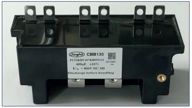
The objective is not simply to replace several capacitors with a single housing. It is to control the geometry of the switching-current path while providing the required capacitance, insulation and heat removal.
Technology and operating principle
Integrating capacitance with the current path
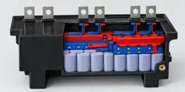
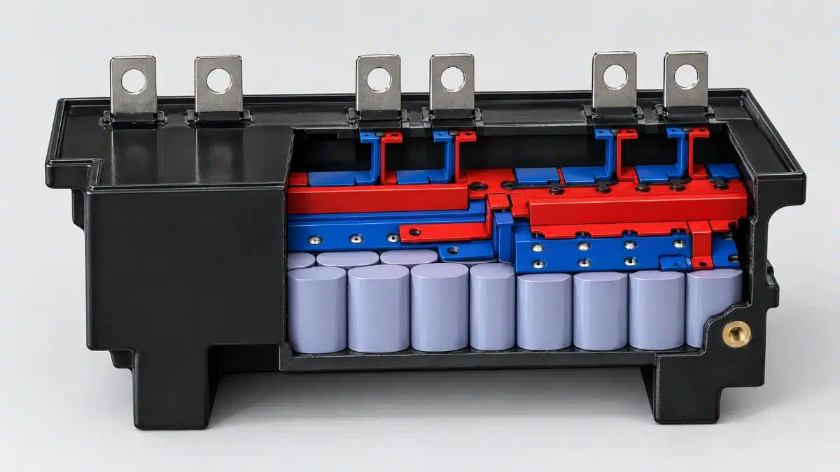
Inside the module, a frame structure accommodates several capacitor cells, usually connected in parallel. Depending on the design, copper bars provide additional current paths.
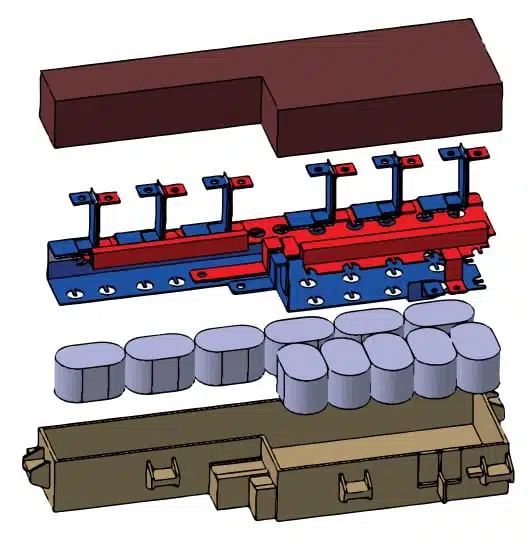
Parallel cells contribute to the total capacitance and distribute current through the assembly. Their arrangement and connections also influence the module’s equivalent series resistance, or ESR, and equivalent series inductance, or ESL.
These parameters have different circuit consequences:
- Capacitance determines the charge available to support the DC link as the power stage draws and returns energy.
- ESR contributes to ripple-related dissipation and the resistive part of the terminal-voltage variation.
- ESL contributes to the voltage developed during fast current transitions.
- External connections add further resistance and inductance beyond the capacitor assembly.
Direct connection to the semiconductor shortens the current path. The benefit depends on the outgoing and return paths together, not simply on the distance from the capacitor housing to the power module. A short connection that leaves a large current-loop area can retain significant inductance.
This is the central relationship behind low-self-inductance DC-link film capacitors: the capacitor construction and its installation must work together. Component ESL and complete commutation-loop inductance are related, but they are not interchangeable.
Polypropylene dielectric and self-healing
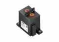
The Jianghai CBB 133 DM and CBB 135 DV module families use polypropylene dielectric and self-healing construction. CBB 133 DM uses a metal housing; CBB 135 DV uses a plastic housing.
In a self-healing metallised film capacitor, a local dielectric breakdown can clear the surrounding metallisation and isolate the affected area. This mechanism allows the remaining active area to continue functioning. It does not remove the need to control voltage, temperature and repetitive electrical stress.
The physical arrangement of the cells and conductors remains important even when the dielectric technology is unchanged. Two assemblies with the same nominal capacitance and voltage can have different parasitic impedance and thermal behaviour.
Electrical comparison at equal voltage and capacitance
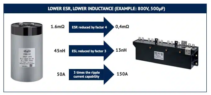
An illustrative comparison uses a cylindrical film capacitor and a module, both at 800 V and 500 µF.
| Parameter | Cylindrical capacitor | Module |
|---|---|---|
| Voltage | 800 V | 800 V |
| Capacitance | 500 µF | 500 µF |
| ESR | 1.6 mΩ | 0.4 mΩ |
| ESL | 45 nH | 13 nH |
| Ripple-current capability | 50 A | 150 A |
At the same stated voltage and capacitance, the module example combines lower ESR and ESL with a higher ripple-current capability. These are example-specific characteristics, rather than ratings for every module in either family.
The comparison highlights why a capacitance-only substitution can miss the purpose of integration. The energy-buffering function can remain nominally unchanged while the resistive, inductive and thermal behaviour changes substantially.
Lower ESR reduces resistive dissipation at a given ripple current. Lower ESL reduces the inductive contribution to terminal-voltage excursions during current transitions. Higher permissible ripple current allows the capacitor assembly to accommodate a greater alternating-current load, subject to its thermal design.
Those effects should not be combined into an assumption that the module necessarily runs cooler at its own maximum current. Increasing current increases dissipation, so the permissible current and the cooling arrangement must be assessed together.
The 13 nH module example is also distinct from the sub-5 nH ESL values available in selected customer-specific module designs. The latter depends on the particular construction and connection geometry; it is not a characteristic that follows automatically from using a module housing.
Construction and thermal integration
The module architecture allows the capacitor shape and terminals to follow the power-stage arrangement. This can reduce the length of high-current connections and simplify assembly by combining functions otherwise distributed across capacitors and busbars.
Thermal integration provides another design variable. Cooling surfaces or coupling to a water-cooling system can support continuous currents of many hundreds of amperes in suitable custom designs. This is a construction-dependent capability, not a universal current rating.
Electrical and thermal optimisation therefore need to proceed together:
- Conductor geometry affects resistance and inductance.
- Cell arrangement affects current distribution.
- Housing and mounting arrangements affect heat transfer.
- Cooling interfaces affect the relationship between dissipation and internal temperature.
- Terminal placement affects both electrical connection and mechanical integration.
A short electrical connection to a semiconductor can also place the capacitor near a heat source. The thermal design must account for heat entering from neighbouring components as well as heat generated inside the capacitor.
Product characteristics that govern selection
CBB 133 DM is a customer-specific module family. Its published characteristics provide a selection framework, while the electrical and mechanical parameters of the final assembly are defined for the particular design.
| Parameter | CBB 133 DM characteristic | Condition |
|---|---|---|
| Rated DC voltage | 750–3000 V DC | Custom design |
| Capacitance | 500–65,000 µF | Custom design |
| Capacitance tolerance | ±5% or ±10% | J or K |
| Operating temperature | −40 to +70 °C | Hotspot ≤85 °C |
| Storage temperature | −40 to +85 °C | — |
| Dielectric dissipation factor | ≤2 × 10⁻⁴ | 20 °C, 100 Hz |
| Life expectancy | 100,000 h | Rated voltage; hotspot ≤70 °C |
| Failure rate | ≤100 FIT | Rated voltage; hotspot ≤70 °C |
| Reference standard | IEC 61071:2007 | — |
The voltage and capacitance ranges describe the family’s custom-design envelope. They should not be read as a promise that every combination is available in every housing or terminal arrangement.
The operating-temperature limit and the lifetime condition also serve different purposes. An allowable hotspot temperature of 85 °C does not make the 100,000 h life-expectancy figure applicable at that temperature. The stated life expectancy is tied to a hotspot temperature no higher than 70 °C at rated voltage.
Life expectancy and failure rate are statistical characteristics. They are not individual service-life guarantees, and neither should be treated as the duration of a completed endurance experiment.
Insulation characteristics
CBB 133 DM has a terminal-to-terminal test voltage of 1.5 times rated DC voltage for 10 s at 20 °C. The terminal-to-case test voltage is at least 3000 V AC for 10 s at 20 °C and 50 Hz.
These withstand-test values concern short-duration insulation stress. They are not continuous operating voltages and do not replace the assessment of the actual DC-link waveform.
The insulation-resistance–capacitance product is at least 5000 MΩ·µF, measured at 20 °C with 100 V DC after 1 min. This characterises insulation leakage under those conditions; it does not determine ripple-current capability.
Ripple current, losses and hotspot temperature
Ripple-current capability is an electrothermal characteristic. Alternating current produces losses inside the capacitor, and the thermal path determines the resulting hotspot temperature.
The manufacturer’s loss relationship is:
where is power loss, ESR is equivalent series resistance and is RMS current.
The corresponding hotspot relationship is:
where is the temperature at the hottest internal position, is ambient temperature, is power loss and is thermal resistance.
These relationships explain why ripple current and cooling cannot be selected independently. Reducing ESR reduces dissipation at a fixed current. Improving the thermal path reduces the temperature rise associated with that dissipation.
A water-cooled arrangement and a naturally cooled assembly therefore require different thermal assessments even if their nominal capacitance and voltage are the same. The thermal resistance must represent the intended installation.
RMS current and repetitive peak current also need separate attention. RMS current drives heating, while peak current and voltage-rise rate impose additional electrical stress on the capacitor and its connections.
Switching behaviour and the role of snubbers
Reducing the inductance between the DC-link capacitor and semiconductor can reduce switching overshoot and ringing. In some integrated arrangements, this can remove the need for an additional snubber capacitor.
Snubber removal should nevertheless be a consequence of the complete switching-loop design, not an assumption attached to the module format. The switching device, connection geometry and operating waveform determine the remaining transient stress.
This distinction matters when interpreting an ESL value. A module’s internal inductance does not include every inductive contribution in the installed converter. Connection hardware and the path through the semiconductor assembly remain part of the commutation loop.
Integration changes the location and distribution of parasitic elements. It does not eliminate them.
Applications and architectural trade-offs
Target applications include high-power frequency converters, electric and hybrid vehicles, traction systems and trains. On-board chargers are another application for custom module integration.
These applications share a need to coordinate the DC-link capacitor with the switching power stage. Their requirements can differ in voltage, capacitance, terminal arrangement, mounting space and cooling.
A custom module is particularly relevant when the electrical interface itself is a design constraint. Terminal positions can follow the semiconductor arrangement, while the cell structure and conductors can be developed around the required current paths.
The trade-off is a closer dependence between the capacitor assembly and the converter’s mechanical architecture. Changes to the semiconductor footprint, bus connection or cooling interface may affect the module design. A discrete arrangement can provide more freedom to rearrange individual components, while an integrated module concentrates more of that work into a coordinated assembly.
Humidity remains an environmental consideration. Prolonged moisture exposure can oxidise electrodes, reduce capacitance and increase losses. A metal or plastic enclosure alone should not be treated as a quantified humidity-endurance characteristic.
Design-in notes for engineers
- Define the terminal interface early. Coordinate capacitor terminals, semiconductor connections and the outgoing and return paths before fixing the mechanical envelope.
- Select voltage against the complete waveform. Include the DC level and superimposed ripple, rather than comparing the nominal bus voltage alone with the capacitor rating.
- Separate RMS and peak-current requirements. Assess continuous heating and repetitive current stress independently.
- Establish the cooling arrangement with the current requirement. Ambient temperature, neighbouring heat sources and the thermal interface all influence hotspot temperature.
- Keep lifetime conditions attached to the lifetime figure. For CBB 133 DM, the 100,000 h expectation applies at rated voltage and a hotspot temperature no higher than 70 °C.
- Treat the semiconductor connection as part of the capacitor design. An extended external connection can offset the intended reduction in parasitic inductance.
- Coordinate mechanical loads. Mounting and terminal arrangements should avoid bending, twisting or sustained stress on the connections.
- Provide controlled discharge. Stored energy and residual terminal voltage require a defined discharge path before handling.
Before design release, validate switching transients, current loading, thermal behaviour, insulation and mechanical integration in the intended converter assembly.
Summary
Custom DC-link film capacitor modules combine energy storage with deliberate control of the current path. Their engineering value lies in the relationship between cell arrangement, conductors, terminals and cooling—not simply in consolidating components into one enclosure.
The 800 V, 500 µF comparison illustrates how equal nominal capacitance and voltage can coexist with different ESR, ESL and ripple-current capability. Selection therefore needs to connect the capacitor’s electrical characteristics to the actual switching loop and thermal installation.
Source
This technical paper is an edited and extended adaptation of the Jianghai Europe white paper “Irreplaceable Modules” by Ole Bjørn, published with the permission of Jianghai Europe. Engineers should refer to the current manufacturer datasheets and the agreed custom-module specification for final design and qualification.
References
- Irreplaceable Modules, Ole Bjørn, Jianghai Europe.
- Film Capacitors · Modules: CBB 133 DM Series, Jianghai Europe, v2025.1.
- Film Capacitors 2026/2027, Jianghai Europe, v2026.2.
- Film Capacitor Modules with Extremely Low ESL, Jianghai Europe.