




Passive Components Blog
No Result
View All Result
  • Home
  • News
    • All
    • Aerospace & Defence
    • Antenna
    • Applications
    • Automotive
    • Capacitors
    • Circuit Protection Devices
    • electro-mechanical news
    • Filters
    • Fuses
    • Inductors
    • Industrial
    • Integrated Passives
    • inter-connect news
    • Market & Supply Chain
    • Market Insights
    • Medical
    • Modelling and Simulation
    • New Materials & Supply
    • New Technologies
    • Non-linear Passives
    • Optoelectronics and Isolation
    • Oscillators
    • Passive Sensors News
    • Resistors
    • RF & Microwave
    • Telecommunication
    • Weekly Digest
    Vishay VJ series surface-mount ceramic safety capacitors with rectangular bodies and metal end terminations

    Vishay Introduces X1 Safety MLCCs for AC Line Filtering

    Illustrative aerospace electronics assembly with board-to-board connectors, coaxial RF cables and optical links.

    Military and Aerospace Interconnect Design: Key Trade-offs

    Samsung Introduces 630V X7T Molded Frame Capacitor for Automotive

    Exxelia Presents Disc Capacitors and Integrated Magnetics for Space

    Vishay 259 PHM-SI cylindrical aluminum electrolytic capacitors with blue insulating sleeves and snap-in terminals

    Vishay Adds 550 V and 600 V Snap-In Capacitors

    illustrative image of film capacitors close to a circuit board

    2026 Capacitor Price Shock: Where Film Capacitors Fit

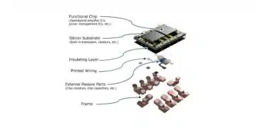
    Exploded view of the Nisshinbo Silicon Motherboard: functional chip, silicon substrate, insulating layer, printed wiring, external passive parts and frame

    Nisshinbo Silicon Motherboard Integrates ICs and Passives

    Murata MGJ2T2 SIP isolated DC-DC converter for SiC gate-drive power

    Murata Unveils Isolated DC-DC for SiC Gate Drives

    Simplified buck, boost, flyback and isolated buck power-stage schematics showing switches, inductors, coupled magnetics, diodes and output capacitors.

    SMPS Topology Selection: From Buck and Boost to Flyback and LLC

    Trending Tags

    • Ripple Current
    • RF
    • Leakage Current
    • Tantalum vs Ceramic
    • Snubber
    • Low ESR
    • Feedthrough
    • Derating
    • Dielectric Constant
    • New Products
    • Market Reports
  • Knowledge Blog
  • Dossiers
    • Aerospace and Defense Passive Components Dossier
    • AI Hardware Dossier
    • Automotive Dossier
    • Industrial Robotics Dossier
    • Power Converter Dossier
    • Capacitor Dossier
    • Circuit Protection Dossier
    • Inductor Dossier
    • Resistor Dossier
    • Silicon Capacitors and Integrated Passives Dossier
  • Suppliers
    • Who is Who
  • PCNS
    • PCNS 2025
    • PCNS 2023
    • PCNS 2021
    • PCNS 2019
    • PCNS 2017
  • Events
  • Home
  • News
    • All
    • Aerospace & Defence
    • Antenna
    • Applications
    • Automotive
    • Capacitors
    • Circuit Protection Devices
    • electro-mechanical news
    • Filters
    • Fuses
    • Inductors
    • Industrial
    • Integrated Passives
    • inter-connect news
    • Market & Supply Chain
    • Market Insights
    • Medical
    • Modelling and Simulation
    • New Materials & Supply
    • New Technologies
    • Non-linear Passives
    • Optoelectronics and Isolation
    • Oscillators
    • Passive Sensors News
    • Resistors
    • RF & Microwave
    • Telecommunication
    • Weekly Digest
    Vishay VJ series surface-mount ceramic safety capacitors with rectangular bodies and metal end terminations

    Vishay Introduces X1 Safety MLCCs for AC Line Filtering

    Illustrative aerospace electronics assembly with board-to-board connectors, coaxial RF cables and optical links.

    Military and Aerospace Interconnect Design: Key Trade-offs

    Samsung Introduces 630V X7T Molded Frame Capacitor for Automotive

    Exxelia Presents Disc Capacitors and Integrated Magnetics for Space

    Vishay 259 PHM-SI cylindrical aluminum electrolytic capacitors with blue insulating sleeves and snap-in terminals

    Vishay Adds 550 V and 600 V Snap-In Capacitors

    illustrative image of film capacitors close to a circuit board

    2026 Capacitor Price Shock: Where Film Capacitors Fit

    Exploded view of the Nisshinbo Silicon Motherboard: functional chip, silicon substrate, insulating layer, printed wiring, external passive parts and frame

    Nisshinbo Silicon Motherboard Integrates ICs and Passives

    Murata MGJ2T2 SIP isolated DC-DC converter for SiC gate-drive power

    Murata Unveils Isolated DC-DC for SiC Gate Drives

    Simplified buck, boost, flyback and isolated buck power-stage schematics showing switches, inductors, coupled magnetics, diodes and output capacitors.

    SMPS Topology Selection: From Buck and Boost to Flyback and LLC

    Trending Tags

    • Ripple Current
    • RF
    • Leakage Current
    • Tantalum vs Ceramic
    • Snubber
    • Low ESR
    • Feedthrough
    • Derating
    • Dielectric Constant
    • New Products
    • Market Reports
  • Knowledge Blog
  • Dossiers
    • Aerospace and Defense Passive Components Dossier
    • AI Hardware Dossier
    • Automotive Dossier
    • Industrial Robotics Dossier
    • Power Converter Dossier
    • Capacitor Dossier
    • Circuit Protection Dossier
    • Inductor Dossier
    • Resistor Dossier
    • Silicon Capacitors and Integrated Passives Dossier
  • Suppliers
    • Who is Who
  • PCNS
    • PCNS 2025
    • PCNS 2023
    • PCNS 2021
    • PCNS 2019
    • PCNS 2017
  • Events
No Result
View All Result
Passive Components Blog
No Result
View All Result

Vishay Introduces X1 Safety MLCCs for AC Line Filtering

20.11.2026
Reading Time: 6 mins read
A A
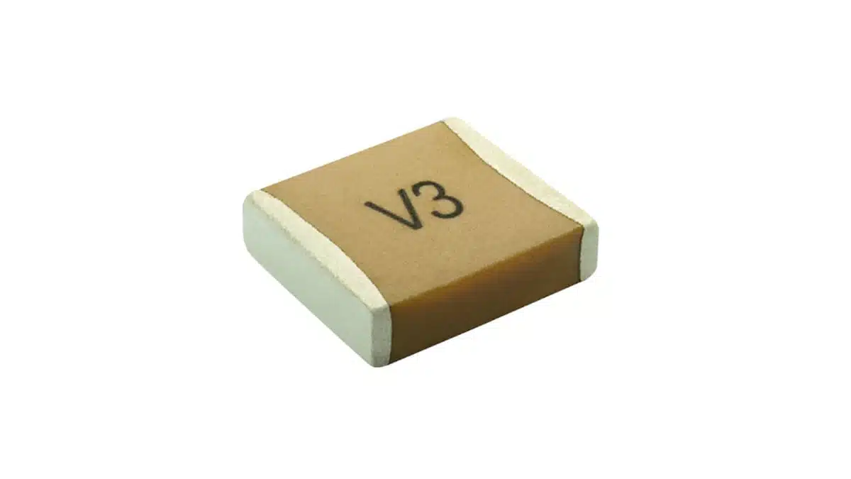
Vishay VJ series surface-mount ceramic safety capacitors with rectangular bodies and metal end terminations

Vishay Intertechnology has introduced the 305 VAC VJ Safety Certified Capacitors series, extending its surface-mount safety MLCC portfolio from 250 VAC to 305 VAC.

The X7R capacitors provide 270 pF to 4.7 nF in a 2220 case for line-to-line interference suppression, with X1 safety certification, a 2 kVDC rating and 5 kV peak impulse capability.

RelatedPosts

Vishay Adds 550 V and 600 V Snap-In Capacitors

Vishay Unveils Top-Side Cooled 35 W Power Resistor

Vishay SMD Power Resistor Sample Kits for High-Power Design

Key features and benefits

  • X1 certification to IEC 60384-14 for mains-connected interference-suppression applications.
  • A 305 VAC rating for line-to-line filtering where the operating voltage requires additional margin beyond a 250 VAC component rating.
  • Capacitance options from 270 pF to 4.7 nF, with ±10% or ±20% tolerance.
  • A 2220 surface-mount package measuring 5.59 mm × 5.08 mm nominal, with a maximum thickness of 2.18 mm.
  • Noble metal electrode construction using a wet build process.
  • Operation from −55 °C to +125 °C.
  • Compatibility with automated pick-and-place assembly and reflow soldering.

Technical highlights

The 305 VAC VJ series uses an X7R dielectric and nickel-barrier terminations with a 100% matte tin finish. The VJ2220 family combines the AC working-voltage rating with separate DC, impulse and voltage-proof characteristics.

ParameterValueConditions or options
Safety classX1IEC 60384-14
Rated AC voltage305 VACX1
Rated DC voltage2000 VDCX1
Peak impulse voltage5000 VX1
Voltage-proof capability2600 VAC60 s
Capacitance range270 pF–4.7 nFX7R
Capacitance tolerance±10% or ±20%K or M code
Operating temperature−55 °C to +125 °C
Temperature characteristic±15%0 VDC applied
Dissipation factor2.5% maximum1.0 VRMS, 1 kHz
Ageing rate1% maximum per decadeX7R

Capacitance and dissipation factor are measured at 1.0 VRMS and 1 kHz. The ±15% temperature characteristic applies from −55 °C to +125 °C with no DC bias applied; it is distinct from the initial capacitance tolerance. Filter selection should account for both characteristics rather than treating the nominal capacitance as a fixed value across temperature.

Safety classification and voltage selection

The capacitors are X1 safety capacitors for across-the-line, differential-mode filtering. Their VDE approval covers 270 pF to 4700 pF at 305 VAC under certificate 40061661, with compliance to IEC 60384-14:2023 and EN IEC 60384-14:2023.

The 305 VAC working rating, 2000 VDC rating, 5000 V peak impulse capability and 2600 VAC/60 s voltage-proof capability serve different selection and test purposes. Operating-voltage selection should use the relevant AC or DC rating, while insulation and transient assessments should address their respective test conditions.

Package and assembly

Mechanical parameterValue
Case size2220
Length5.59 ±0.20 mm
Width5.08 ±0.25 mm
Maximum thickness2.18 mm
Termination length0.25–0.76 mm
Tape width12 mm
Reel format7-inch
Quantity per reel1000

The package supports reflow assembly. The 2220 case should not be wave soldered, and controlled heating and cooling are important to avoid thermally induced ceramic cracks.

Typical applications

The principal circuit position is a line-to-line capacitor in an AC-input interference-suppression network. The 305 VAC rating governs the working-voltage selection, while the 270 pF to 4.7 nF range provides capacitance options for the suppression network.

Target applications include:

  • Power supplies and AC line filters in energy and industrial equipment.
  • Consumer devices and mains-connected appliances.
  • Isolation-related circuits.
  • Lightning-strike and voltage-surge protection circuits.

In an EMI filter, the X1 device occupies the across-the-line position for differential-mode filtering. The selected capacitance, working voltage and impulse capability need to match that circuit position and its electrical stresses.

Design-in notes for engineers

  • Match the safety class to the connection point. X-class capacitors serve across-the-line filtering; line-to-ground filtering uses Y-class components.
  • Use the safety-capacitor land pattern. The recommended drawing dimensions are A = 5.80 mm, B = 1.50 mm and C = 4.20 mm, with an optional 0.5 mm corner radius. Transfer these dimensions using the drawing’s geometry.
  • Include PCB cleanliness in the insulation design. Flux residue, solder balls and surface contamination can reduce the arcing inception voltage between opposing terminations.
  • Consider a slot between the pads where cleaning or coating beneath the capacitor is required. Rounded inward-facing pad edges and adequate pad separation also form part of the high-voltage layout guidance.
  • Control the reflow profile and allow natural cooling. Direct soldering-iron attachment is not recommended because thermal shock can crack the ceramic.
  • Retain the complete ordering code through procurement and production. The ordering structure distinguishes capacitance, tolerance, termination, voltage, marking, packaging and the required process code.
  • Validate the final component selection, PCB layout and assembly process under the actual operating conditions before production release.

Availability

Samples and production quantities are available, with a lead time of 12 weeks at introduction in November 2026. The series is RoHS-compliant, halogen-free and Vishay Green.

Further reading

  • 12 Things You Need to Know About Preventing Overloads with Safety Capacitors
  • Safety Capacitors for EV/HEV Applications

Source

This article is based on the Vishay product announcement and official product documentation. Engineers should refer to the current manufacturer datasheet for final design and qualification.

References

  1. 305 VAC VJ Safety Certified Capacitors — Surface Mount Multilayer Ceramic Chip Capacitors for Safety Certified Applications, Vishay Vitramon, April 7, 2026.
  2. 305 VAC VJ Safety Certified Capacitors — Product Information, Vishay.
  3. VDE Certificate — 305 VAC VJ Safety Certified Capacitors, Vishay Vitramon, April 15, 2026.
  4. Soldering Recommendations — Surface Mount Multilayer Ceramic Chip Capacitors, Vishay Vitramon, November 11, 2024.
  5. Safety Capacitors — EMI Safety Capacitor Solutions, Vishay, 2023.
  6. Safety Certified MLCCs Extend Voltage Ratings to 305 VAC, Vishay Vitramon, November 2026.
Related

Recent Posts

Samsung Introduces 630V X7T Molded Frame Capacitor for Automotive

19.11.2026
30

Exxelia Presents Disc Capacitors and Integrated Magnetics for Space

18.11.2026
32
Vishay 259 PHM-SI cylindrical aluminum electrolytic capacitors with blue insulating sleeves and snap-in terminals

Vishay Adds 550 V and 600 V Snap-In Capacitors

18.11.2026
21
illustrative image of film capacitors close to a circuit board

2026 Capacitor Price Shock: Where Film Capacitors Fit

17.11.2026
40
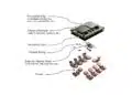
Exploded view of the Nisshinbo Silicon Motherboard: functional chip, silicon substrate, insulating layer, printed wiring, external passive parts and frame

Nisshinbo Silicon Motherboard Integrates ICs and Passives

17.11.2026
23
Murata MGJ2T2 SIP isolated DC-DC converter for SiC gate-drive power

Murata Unveils Isolated DC-DC for SiC Gate Drives

17.11.2026
26
Simplified buck, boost, flyback and isolated buck power-stage schematics showing switches, inductors, coupled magnetics, diodes and output capacitors.

SMPS Topology Selection: From Buck and Boost to Flyback and LLC

16.11.2026
38
Littelfuse AK-FB and AK-A high-power TVS diodes in axial-leaded packages

Littelfuse Introduces TVS Diodes for HVDC Protection

16.11.2026
17
VACUUMSCHMELZE VACODUR Max cobalt-iron lamination material illustrated as thin metallic rotor and stator stacks.

VACUUMSCHMELZE Introduced VACODUR Max Cobalt-Iron Alloy for Motor Laminations

12.11.2026
80

Upcoming Events

Nov 24
16:00 - 17:00 CET

Select the Correct Components for Your DC/DC Converter

Dec 1
16:00 - 17:00 CET

Developing low-noise mixed-signal systems

Dec 8
16:00 - 17:00 CET

WE-CCMF: Design Principles, Layout Guidelines and Measurement Results for High-Speed EMI Filtering

View Calendar

Popular Posts

  • Buck Converter Design and Calculation

    0 shares
    Share 0 Tweet 0
  • September 2026 Interconnect, Passives and Electromechanical Components Market Insights

    0 shares
    Share 0 Tweet 0
  • Boost Converter Design and Calculation

    0 shares
    Share 0 Tweet 0
  • Capacitor Charging and Discharging

    0 shares
    Share 0 Tweet 0
  • RF Connector Types: How To Choose the Right One

    0 shares
    Share 0 Tweet 0
  • Passive Low Pass Filters: Fundamentals and EMI Design

    0 shares
    Share 0 Tweet 0
  • LLC Resonant Converter Design and Calculation

    0 shares
    Share 0 Tweet 0
  • Flyback Converter Design and Calculation

    0 shares
    Share 0 Tweet 0
  • Capacitor Symbols

    0 shares
    Share 0 Tweet 0
  • MLCC and Ceramic Capacitors

    0 shares
    Share 0 Tweet 0

Newsletter Subscription


Passive Components Blog

© 2015–2026
All rights reserved

  • Home
  • Privacy Policy
  • EPCI Membership & Advertisement
  • About

No Result
View All Result
  • Home
  • Knowledge Blog
  • Dossiers
  • PCNS

© 2015–2026
All rights reserved