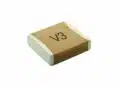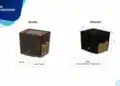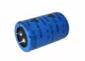

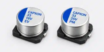





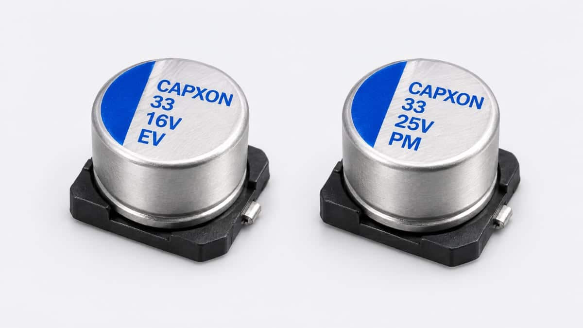
CapXon has introduced a 6.3 × 3.9 mm case size for its PM conductive polymer and EV aluminium electrolytic capacitor families.
The addition addresses height-restricted electronics, giving designers two capacitor technologies to consider within the same nominal diameter and height envelope.
Key features and benefits
- Nominal case dimensions of 6.3 mm diameter × 3.9 mm height address component-height constraints.
- The PM family uses solid conductive polymer technology in a surface-mount package.
- The EV family provides surface-mount aluminium electrolytic capacitors with several capacitance and voltage combinations in the 3.9 mm case height.
- EV operating temperature spans −55 °C to +105 °C, with endurance of 1,000 hours at +105 °C and rated voltage.
- EV capacitance tolerance is ±20%, measured at 120 Hz and +20 °C.
Technical highlights
Two technologies in the new case size
The PM and EV families provide different technology options for space-critical assemblies. PM uses a solid conductive polymer electrolyte, while EV belongs to the aluminium electrolytic family.
Selection should start with the required capacitance, operating voltage and ripple-current spectrum, rather than the mechanical envelope alone. Electrical ratings and test conditions remain specific to each series and ordering code.
EV ratings in the 6.3 × 3.9 mm package
The EV options below share a nominal 6.3 mm diameter and 3.9 mm height. Their ripple-current ratings apply at +105 °C and 120 Hz.
| Part number | Rated voltage | Capacitance | Ripple current |
|---|---|---|---|
| EV101M6R3E039ETR | 6.3 V DC | 100 µF | 52 mA RMS |
| EV470M010E039ETR | 10 V DC | 47 µF | 40 mA RMS |
| EV330M016E039ETR | 16 V DC | 33 µF | 35 mA RMS |
| EV470M016E039ETR | 16 V DC | 47 µF | 44 mA RMS |
| EV220M025E039ETR | 25 V DC | 22 µF | 33 mA RMS |
| EV330M025E039ETR | 25 V DC | 33 µF | 42 mA RMS |
| EV220M035E039ETR | 35 V DC | 22 µF | 36 mA RMS |
These combinations make voltage rating and capacitance a coupled selection decision. Within the same package, the 6.3 V option provides 100 µF, while the 35 V option provides 22 µF. At 16 V and 25 V, alternative capacitance values also have different ripple-current limits.
Ripple-current frequency matters
EV ripple-current correction factors depend on frequency. For the capacitance values in the table, the multipliers are 0.8 at 50/60 Hz, 1 at 100/120 Hz, 1.2 at 500 Hz, 1.3 at 1 kHz and 1.5 at 10 kHz.
The PM family uses a different frequency-correction schedule. Its multipliers are 0.05 from 120 Hz to below 1 kHz, 0.3 from 1 kHz to below 10 kHz, 0.7 from 10 kHz to below 100 kHz, and 1 from 100 kHz to below 300 kHz.
A ripple-current comparison therefore needs matching frequency and temperature conditions. A headline current value without its measurement conditions is insufficient for selecting between the technologies.
Endurance is a test condition
EV endurance is 1,000 hours at +105 °C with rated voltage applied. After this test, capacitance change must remain within ±25% of the initial measured value for ratings up to 16 V, or ±20% for ratings of 25 V and above. Dissipation factor must remain within 200% of its initial limit, and leakage current must remain within its initial limit.
The PM family has an endurance test of 2,000 hours at +105 °C with rated voltage applied. Its acceptance criteria include capacitance change within ±20% of the initial value, with ESR and dissipation factor within 150% of their initial limits.
These test durations are not direct service-life predictions. Ambient temperature, ripple current, applied voltage and the assembly’s thermal conditions affect capacitor performance and lifetime.
Application fit
Target applications are height-restricted, high-density electronic assemblies. The 3.9 mm nominal height addresses vertical clearance, while the electrical requirements determine the appropriate technology and ordering code.
For EV selection, the available combinations extend from 100 µF at 6.3 V to 22 µF at 35 V in this case size. Designs requiring a higher voltage rating must therefore assess the corresponding capacitance and ripple-current capability rather than treating all 6.3 × 3.9 mm devices as interchangeable.
The mechanical envelope also extends beyond the cylindrical can. The EV outline gives base dimensions A and B of 6.6 ±0.2 mm and dimension C of 7.2 ±0.2 mm. PCB placement should use the complete package outline, not a circular keep-out based on the can diameter.
Design-in notes for engineers
- Select the exact capacitance–voltage combination before assigning the footprint and bill-of-materials entry.
- Assess applied voltage, ripple current and ambient temperature together.
- Apply the appropriate series-specific frequency correction to the ripple-current requirement.
- Include the complete package outline, dimensional tolerances and enclosure clearance in the layout check.
- Treat endurance-test duration separately from the equipment’s required service interval.
- Validate final selection under the actual electrical, thermal and assembly conditions before production release.
Further reading
Source
This article is based on the CapXon product announcement and official product documentation. Engineers should refer to the current manufacturer datasheet for final design and qualification.
References
- Product Update: Maximize PCB Space with CapXon’s Ultra-Low Profile Polymer Capacitor – 6.3 × 3.9 mm, CapXon, 5 August 2026.
- EV Series — 3.9 Height Datasheet, CapXon.
- PM Series — Low Height Type, CapXon, version 006.