








Samsung Electro-Mechanics has started mass production of an automotive molded frame capacitor (MFC) in 2220 size with 1.2 µF, 630 V and X7T characteristics.
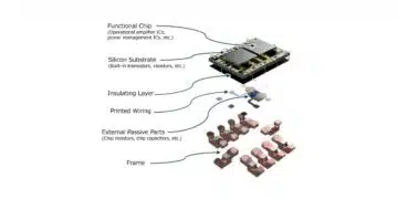
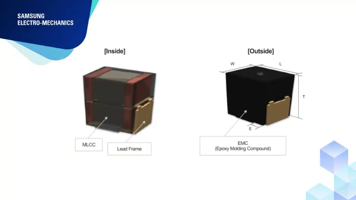
The Samsung Electro-Mechanics part CL55Z125MH6MPN is a 2-stack MFC: two MLCCs are connected by a lead frame and enclosed in epoxy molding compound (EMC). It targets high-voltage positions in electric vehicles, where battery voltages are moving from 400 V to 800 V for fast charging at 11 kW and 22 kW.
Key features and benefits
- 1.2 µF nominal capacitance with ±20% tolerance.
- 630 V DC rated voltage.
- X7T temperature characteristic across −55 °C to +125 °C.
- Two-stack molded frame MLCC construction.
- Package dimensions of 6.25 ±0.40 mm × 5.15 ±0.40 mm × 6.00 ±0.40 mm.
- Automotive AEC-Q200 qualification.
- Mass-production status, with samples and technical support available for customer-specific designs.
Technical highlights
Electrical characteristics and package dimensions
The CL55Z125MH6MPN# extends the automotive MFC family with a 630 V DC X7T option. Its 2220 size designation corresponds to the 5750 metric size code; layout and mechanical integration should use the component’s actual package dimensions.
| Parameter | Value |
|---|---|
| Product designation | CL55Z125MH6MPN# |
| Construction | MFC, two-stack |
| Nominal capacitance | 1.2 µF |
| Capacitance tolerance | ±20% |
| Rated voltage | 630 V DC |
| Temperature characteristic | X7T |
| Operating temperature | −55 °C to +125 °C |
| Size code | 2220 / 5750 |
| Length | 6.25 ±0.40 mm |
| Width | 5.15 ±0.40 mm |
| Thickness | 6.00 ±0.40 mm |
| Qualification | AEC-Q200 |
| Production status | Mass production |
The complete packaged ordering code is CL55Z125MH6MPNF. The final character selects the packaging option; F denotes embossed tape on a 13-inch reel.
Temperature behaviour and effective capacitance
The X7T characteristic permits capacitance variation of −33% to +22% across the operating-temperature range. This temperature characteristic is distinct from the component’s ±20% nominal capacitance tolerance.
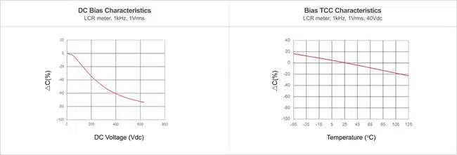
The 1.2 µF value is a nominal capacitance, rather than a fixed in-circuit value. Class II ceramic capacitance decreases with applied DC voltage, while AC measurement amplitude and operating frequency also affect the measured response. MLCC DC-bias behaviour therefore matters when establishing the capacitance available for voltage smoothing.
Molded frame construction
The package combines epoxy molding compound with a conductive lead frame. The molded frame structure absorbs deformation stress associated with PCB bending and addresses the mechanical path between the ceramic capacitor and the board.
Package geometry also matters in high-voltage layouts. Creepage and clearance should be assessed at the assembled-board level, including the capacitor terminals, solder joints and surrounding conductors.
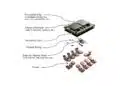
Inside the molded body, two MLCCs are stacked and joined by a lead frame, which lifts the ceramic body above the board and takes part of the mechanical stress. The EMC encloses the stack and extends the surface path between the terminals. Creepage and clearance distances become more important as battery voltage rises, because the terminal spacing of a standard 2220 MLCC is fixed by its body.
Capacitance Under DC Bias and Temperature
The characteristic curves show the usual class II behaviour. The capacitance change at 630 V DC is about -73 %, and the bias curve falls steadily with voltage. Over temperature, measured at 40 V DC, the change is about +17 % at -55 °C and about -22 % at 125 °C.
The effective capacitance at the operating voltage follows from the curve:
With ΔC = -73 % at 630 V, the 1.2 µF part gives about 0.32 µF. At lower DC voltage, for example on a smoothing position at part of the rated voltage, the retained capacitance is higher, so the design point matters more than the nominal value.
Typical applications and application fit
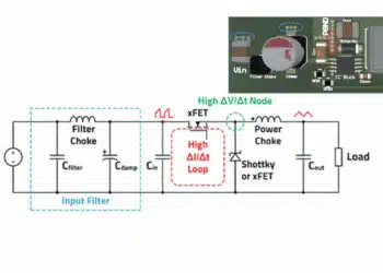
The principal target application is voltage smoothing on the high-voltage battery side of automotive power electronics. Selection depends on the voltage across the capacitor, the effective capacitance at that operating point and the temperature rise under the circuit’s ripple-current waveform.
The 630 V DC rating governs the component voltage, not the nominal voltage label of the vehicle platform. Working voltage, superimposed ripple, transients and fault conditions should be assessed together before fixing the capacitor arrangement.
The wider automotive MFC family also includes the following mass-produced options:
| Construction | Size code | Capacitance | Rated voltage |
|---|---|---|---|
| Single-type MFC | 1210 | 2.2 µF / 4.7 µF | 100 V |
| Two-stack C0G MFC | 2220 | 54 nF | 1,000 V DC |
| Two-stack X7T MFC | 2220 | 1.2 µF | 630 V DC |
The C0G CL55C543JI6MPN# targets resonant high-voltage battery-charging circuits, including (C)LLC DC-DC converters. It serves a different circuit requirement from the X7T voltage-smoothing component: dielectric behaviour and capacitance requirements should guide the choice alongside rated voltage.
Design-in notes for engineers
- Establish the required effective capacitance at the intended DC voltage, temperature, AC amplitude and frequency, rather than sizing the smoothing network from nominal capacitance alone.
- Assess ESR, ripple-current heating and ambient temperature together. Evaluate temperature rise using the intended current waveform and board assembly.
- Use the actual package dimensions and their tolerances for layout, enclosure clearance and assembly planning.
- Include terminal geometry, solder joints and nearby copper in the creepage and clearance assessment.
- Check board deformation during assembly and handling as part of the mechanical design.
- Validate the final selection under actual operating conditions before production release.
Further reading
- Samsung Releases Automotive Molded 2220 1kV C0G MLCC
- Samsung 100V Molded Frame MLCC Targets 48V AI Server PSUs
- DC and AC Bias Dependence of MLCC Capacitors Including Temperature Dependence
Source
This article is based on the Samsung Electro-Mechanics product announcement and official product documentation. Engineers should refer to the current manufacturer datasheet for final design and qualification.
References
- Samsung Electro-Mechanics Launches an Automotive X7T 1.2uF 630V 2-Stack MFC (Molded Frame Capacitor), Samsung Electro-Mechanics, 18 November 2026.
- CL55Z125MH6MPN — Component Library Datasheet, Samsung Electro-Mechanics.
- CL55Z125MH6MPN# — Product Specifications, Samsung Electro-Mechanics.
- Multilayer Ceramic Capacitors — Part II: Automotive, Samsung Electro-Mechanics.
- Molded Frame Capacitor, Samsung Electro-Mechanics.
- MLCC — Products and Technical FAQ, Samsung Electro-Mechanics.
- CL55C543JI6MPN# — Product Specifications, Samsung Electro-Mechanics.
- Launch of the Automotive MFC (2220 inch C0G 1000V 54 nF), Samsung Electro-Mechanics, 22 October 2025.