Passive Components Blog
No Result
View All Result
  • Home
  • NewsFilter
    • All
    • Aerospace & Defence
    • Antenna
    • Applications
    • Automotive
    • Capacitors
    • Circuit Protection Devices
    • electro-mechanical news
    • Filters
    • Fuses
    • Inductors
    • Industrial
    • Integrated Passives
    • inter-connect news
    • Market & Supply Chain
    • Market Insights
    • Medical
    • Modelling and Simulation
    • New Materials & Supply
    • New Technologies
    • Non-linear Passives
    • Oscillators
    • Passive Sensors News
    • Resistors
    • RF & Microwave
    • Telecommunication
    • Weekly Digest

    Nvidia Vera Rubin: Why One AI Rack Needs So Many More MLCC Capacitors

    Stackpole Introduces 1400A Busbar Shunt Resistors

    Tecate Unveils High‑temp 105C Supercapacitors for Harsh‑Environment Designs

    Bourns Expands 1000V High‑Power Fuses for Semiconductor and Battery Protection

    Passive Components in 2026: From Invisible Commodity to Design Parameter

    Bourns Introduces High Current Chip Ferrite Beads for Dense Power Rails

    Wk 22 Electronics Supply Chain Digest

    Vishay Releases High‑Current Radial Inductors up to 209 A

    May 2026 Interconnect, Passives and Electromechanical Components Market Insights

    Trending Tags

    • Ripple Current
    • RF
    • Leakage Current
    • Tantalum vs Ceramic
    • Snubber
    • Low ESR
    • Feedthrough
    • Derating
    • Dielectric Constant
    • New Products
    • Market Reports
  • VideoFilter
    • All
    • Antenna videos
    • Capacitor videos
    • Circuit Protection Video
    • Filter videos
    • Fuse videos
    • Inductor videos
    • Inter-Connect Video
    • Non-linear passives videos
    • Oscillator videos
    • Passive sensors videos
    • Resistor videos

    Current Sense Transformer Datasheet and Design‑in Guide

    Designing a USB Type‑C Flyback Planar Transformer with Frenetic’s Planar Tool

    Magnetics Design in High‑Frequency GaN Converters

    Qi2 Wireless Charging: Inductors, Capacitors and EMC Filters

    Two‑capacitor paradox explained for engineers

    Capacitances of Nonlinear MLCCs: What Datasheets Don’t Tell You

    Tapped Inductor Buck Converter Fundamentals

    Planar vs Conventional Transformer: When it Make Sense

    Modeling Fringing Field Losses in Inductors & Transformers

    Trending Tags

    • Capacitors explained
    • Inductors explained
    • Resistors explained
    • Filters explained
    • Application Video Guidelines
    • EMC
    • New Products
    • Ripple Current
    • Simulation
    • Tantalum vs Ceramic
  • Knowledge Blog
  • DossiersNew
  • Suppliers
    • Who is Who
  • PCNS
    • PCNS 2025
    • PCNS 2023
    • PCNS 2021
    • PCNS 2019
    • PCNS 2017
  • Events
No Result
View All Result
Passive Components Blog
No Result
View All Result

How to Process Through-Hole Components by Reflow Assembly

22.5.2026
Reading Time: 4 mins read
A A

This podcast by Würth Elektronik explains conditions and processes how to mount through-hole components by reflow.

Because of fast assembling and small sizes, designers are turning to surfance mount technology on their PCBs.

RelatedPosts

Qi2 Wireless Charging: Inductors, Capacitors and EMC Filters

Würth Elektronik Presents New Bidirectional Digital Isolators

Würth Elektronik Introduces Compact Flat-wire SMT Power Inductors for Automotive

Although there are still through-hole (THT) components that need to be soldered by Wave, Through-Hole Reflow (THR), allows designers to solder the Through-Hole Components together with the surfance mount parts in the Reflow Oven, thus canceling the whole Wave Soldering Process; saving time and money.

Enhancing PCB Design with Through-Hole Reflow (THR) Technology

This presentation explores the integration of Through-Hole Reflow (THR) technology in Printed Circuit Board (PCB) design and manufacturing. It highlights the evolution of PCB assembly from traditional through-hole components to modern Surface Mount Technology (SMT), while emphasizing the benefits, process optimizations, and quality considerations associated with THR.

1. Introduction

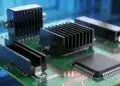
The evolution of PCB technology has transitioned from large, bulky through-hole components to compact SMT. However, certain components such as connectors necessitate robust mechanical stability, achievable through THR. This paper delves into the rationale, requirements, and processes involved in THR.

2. The Necessity of Through-Hole Components

Despite the prevalence of SMT, through-hole components are essential for:

  • High mechanical stress applications
  • Connectors requiring strong insertion and withdrawal forces
  • High current carrying capabilities

3. Material and Design Requirements

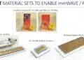
3.1 Housing Material

  • Temperature Resistance: Use of Liquid Crystal Polymer (LCP) for high thermal stability up to 260°C.
  • Moisture Sensitivity: LCP offers low moisture absorption (MSL1), reducing defects such as voids during reflow.

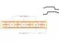
3.2 Structural Modifications

  • Standoffs: Facilitate airflow, solder paste deposition, and visual inspection post-soldering.
  • Pin Adjustments: Optimal pin protrusion (0.5 mm) ensures mechanical stability and effective solder joint formation.

4. PCB Layout and Stencil Design

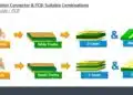
4.1 Via and Pad Design

  • Calculation of via volume to ensure adequate solder paste fill.
  • Adjustment of pad sizes for optimal thermal and electrical performance.

4.2 Stencil Aperture Design

  • Recommendations for stencil thickness (150 µm).
  • Aperture shapes (round, rectangular, overprint designs) tailored to component geometry and paste volume requirements.

5. THR Process Stages

5.1 Solder Paste Application

  • Manual or automated stencil printing ensuring consistent paste deposition.

5.2 Component Placement

  • Use of pick-and-place machines complemented by manual placement for larger components.

5.3 Reflow Soldering

  • Reflow profiles aligned with component thermal mass and paste characteristics.

6. Quality Assurance: IPC-A-610 Standards

  • Class I: General electronics with minimal reliability requirements.
  • Class II: Industrial products with continuous performance expectations.
  • Class III: High-reliability applications (e.g., aerospace, medical devices).

6.1 Solder Joint Criteria

  • Minimum 75% via fill for Class II and III.
  • Visual inspection facilitated by standoffs and AOI systems.

7. Advantages of THR Technology

  • Mechanical Robustness: Enhanced stability for connectors and heavy components.
  • Process Efficiency: Single reflow process eliminates the need for wave soldering.
  • Cost-effectiveness: Reduced production steps lead to lower operational costs.

8. Summary

THR technology bridges the gap between traditional through-hole robustness and SMT efficiency. By adapting component materials, PCB layout, and reflow processes, manufacturers can achieve superior mechanical and electrical performance while optimizing production costs.

Related

Source: Würth Elektronik

Recent Posts

Heatsink Design and Thermal Interface Materials for Reliable Electronics

27.4.2026
84

Würth Elektronik Introduces Lead-Free SMT Spacers

11.2.2026
83

Coaxial Connectors and How to Connect with PCB

17.12.2025
708

PCB Manufacturing, Test Methods, Quality and Reliability

17.12.2025
311

Murata Releases World’s First Inner Cavity-Structure Ultra-Low-Loss LCP Flexible Substrate

10.12.2025
138

Connector PCB Design Challenges

3.10.2025
89

Panasonic Industry to Double Production of MEGTRON PCB Materials

15.9.2025
105

Glass Core Technology Breakthrough Potential for High-Speed Interconnects

5.1.2026
256

What Track Width To Use When Routing PCB

6.6.2025
173

Upcoming Events

Jun 2
16:00 - 17:00 CEST

Calculation, Simulation and Measurement of 800V EMC Filters

Jun 16
16:00 - 17:00 CEST

EMC with EMC – EMC‑compliant design with electromechanical connectors

View Calendar

Popular Posts

  • Buck Converter Design and Calculation

    0 shares
    Share 0 Tweet 0
  • Boost Converter Design and Calculation

    0 shares
    Share 0 Tweet 0
  • Flyback Converter Design and Calculation

    0 shares
    Share 0 Tweet 0
  • MLCC and Ceramic Capacitors

    0 shares
    Share 0 Tweet 0
  • LLC Resonant Converter Design and Calculation

    0 shares
    Share 0 Tweet 0
  • Capacitor Charging and Discharging

    0 shares
    Share 0 Tweet 0
  • What Electronics Engineer Needs to Know About Passive Low Pass Filters

    0 shares
    Share 0 Tweet 0
  • Dual Active Bridge (DAB) Topology

    0 shares
    Share 0 Tweet 0
  • Ripple Current and its Effects on the Performance of Capacitors

    3 shares
    Share 3 Tweet 0
  • SEPIC Converter Design and Calculation

    0 shares
    Share 0 Tweet 0

Newsletter Subscription


Passive Components Blog

© EPCI - Leading Passive Components Educational and Information Site

  • Home
  • Privacy Policy
  • EPCI Membership & Advertisement
  • About

No Result
View All Result
  • Home
  • Knowledge Blog
  • Dossiers
  • PCNS

© EPCI - Leading Passive Components Educational and Information Site

This website uses cookies. By continuing to use this website you are giving consent to cookies being used. Visit our Privacy and Cookie Policy.
Go to mobile version