


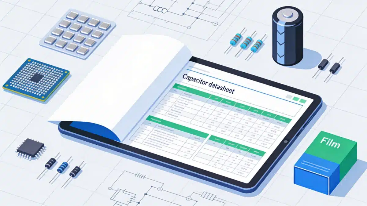
Identifying a component that meets the requirements of an application is a critical step in the designing of electronic circuits. The performance characteristics of any electronic component are provided by manufacturers in product data sheets. This makes a data sheet one of the most useful resources for circuit designers and engineers. This article provides a brief navigation and guidelines about capacitor datasheets and information that you can find there.
Key Takeaways
- Understanding how to read a capacitor data sheet is essential for selecting the right components in electronic circuits.
- Capacitor data sheets typically include performance characteristics, applications, limitations, and electrical parameters.
- Key sections in a data sheet cover electrical characteristics, temperature effects, mechanical fit, and mounting guidelines.
- Safety and environmental considerations provide crucial information regarding the usage and disposal of capacitors.
- By knowing the structure of a data sheet, designers can efficiently extract the information they need for reliable circuit performance.
Capacitors are used in electronic circuits for a wide range of applications including coupling, timing, filtering, decoupling, and wave shaping.
These passive components come in a wide array of shapes, sizes, and designs, and it is usually not easy to identify a component that meets the specific requirements of an application. In most electronic circuits, the overall performance of a circuit is greatly determined by the choice of capacitors.
Despite their usefulness, data sheets can contain a lot of information making it difficult for users to extract the details they require for a given component. A typical capacitor data sheet provides the following information about a component:
- Performance characteristics
- Typical applications
- Limitations of a component
In this guide, we will provide you with tips that can help you to get the most from a capacitor’s data sheet. So, where do you get the right data sheet from? Capacitor data sheets are usually available on manufacturer’s website. Alternatively, you can soon easily download any capacitor data sheet from here. It is important to double check the model number and date of publication to make sure that you are using the right data sheet.
Capacitor data sheets, much like other product data sheets, vary in design and layout depending on the manufacturer. In this guide, we will explore different sections of a typical capacitor data sheet.
Overview
This section summarizes characteristics, features, and typical applications of a component.
Applications
Most manufacturers provide examples of applications that a capacitor can be used for. This section helps circuit designers to find components that are suitable for their applications with ease. This list is usually not exhaustive.
Electrical Characteristics
When your datasheet shows a table called “Electrical characteristics”, “Specifications” or similar, use this section to understand what each listed parameter means and how it affects your design.
This section provides electrical parameters that are of interest to circuit designers. Some parameters are provided directly in the data sheet while others are not. It is important to note that most of these parameters are given at specific conditions.
Many datasheets present the key electrical parameters in a table with columns such as “Parameter”, “Conditions”, “Min”, “Typ”, “Max” and “Unit”. For each row in that table (for example, capacitance at a given frequency and temperature, ESR at a given frequency, or leakage current after a specified time), use the parameter‑specific subsections below to understand how that value is defined and how it should be applied in your circuit.
Voltage
This is one of the key parameters to consider when selecting a capacitor for your application. For most types of capacitors, manufacturers specify voltage characteristics in terms of rated voltage, surge voltage, operating voltage, transient voltage, reverse voltage, and ripple voltage. The rated voltage specifies the maximum peak voltage value that may be applied between the terminals of a component. This nominal voltage is usually indicated on a component by the manufacturer. In comparison, the operating voltage specifies a range of acceptable voltages that may be applied to a component without damaging it.
Most capacitor data sheets specify the capacitance of a component in terms of rated capacitance, AC/DC capacitance, and charge-discharge proof properties. Details on how the capacitance of a component varies with temperature and frequency are usually provided under this subsection.
For some types of capacitors, the capacitance of a component can change significantly over time. The irreversible changes mainly depend on the characteristics of the dielectric material used. The rate at which the capacitance of a component drifts is dependent on the temperature variations that a component is exposed to. The average variation in capacitance over a temperature range is usually described in terms of temperature coefficient. In most data sheets, these variations are provided in form of performance curves.
Equivalent series resistance (ESR)
For a typical equivalent circuit diagram, the equivalent series resistance is the resistive component of the circuit. Just like capacitance and dissipation factor, this parameter is significantly dependent on variations in temperature and frequency. The ESR and the dissipation factor of a capacitor are closely related. In most data sheets, the ESR characteristics of a component are provided in form of performance curves.
The main contributors to the total impedance of a capacitor vary depending on the capacitor technology. The magnitude of impedance depends on the individual reactive and resistive components of a capacitor’s equivalent circuit diagram. The three contributors-inductive reactance, capacitive reactance, and equivalent series resistance- vary depending on the frequency of operation. The last two are also dependent on temperature. In most data sheets, the impedance characteristics of a capacitor are usually provided in form of performance curves.
This electrical parameter describes the relationship between the effective power and the reactive power when a sinusoidal voltage is applied to a component. If we consider a typical equivalent circuit diagram, this parameter relates the capacitive reactance component and the equivalent series resistance. The variation of this parameter with frequency and temperature is usually specified in the data sheet, usually in form of performance curves.
Equivalent series inductance (ESL)
ESL is one of the key components of a basic equivalent circuit diagram of a typical capacitor. This parameter is primarily determined by the internal design of a component and its terminal configuration. The equivalent series inductance of a component is relatively independent of temperature and frequency.
This parameter depends on many factors including the design of a component, internal temperature, and applied voltage. The storage time and conditions significantly determine the initial leakage current of a component. In most data sheets, the leakage current characteristics of a capacitor are provided in form of performance curves.
A current flow through a device when an AC voltage is applied, and it is equivalent to the root-mean-square value of the pulsating current. This current causes power losses and determines the self-heating properties of a component. For most capacitors, the circuit designer is expected to calculate the maximum ripple current.
Some of the factors that one should consider when determining the maximum permissible current value include ambient temperature, thermal resistance, equivalent series resistance, and cooling methods used. In most data sheets, manufacturers provide rated ripple current value at specific temperature and frequency conditions.
This parameter is greatly determined by the design of a component and varies from one type of capacitor to another. For aluminum electrolytic capacitors, most manufacturers use insulating sleeves to boost breakdown strengths.
Temperature Characteristics
Refer to this section whenever you need to check how capacitor performance changes with operating temperature and whether a given part will tolerate your application environment.
Most performance parameters of a capacitor are significantly dependent on the temperature at which a component is operated. The data sheet specifies the temperature range for which a component is designed. It also provides information on how changes in temperature affect other parameters, usually in form of performance curves.
Other performance characteristics that are of interest to circuit designers include the following:
- Insulation resistance
- Insertion loss
- Aging rate
Performance graphs
Most capacitor parameters vary depending on conditions such as temperature and frequency. For such parameters, manufacturers use performance curves to describe the characteristics of a component. The circuit designer can determine a specific value for such a parameter by reading the value that corresponds to conditions at which the component will be used.
Mechanical Characterization
Dimensions
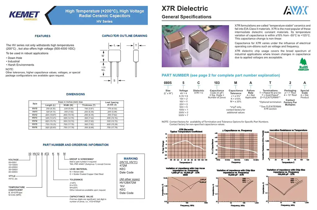
Use this section whenever you are checking case size, lead spacing or package outline from the “Dimensions” tables and drawings in a datasheet and need to confirm mechanical fit on your PCB.
When designing a circuit, one of the key things to consider is the size of a component. Manufacturers provide this information to enable you to select a component that meets the space requirements of your circuit. The size is usually specified in both inches and millimetres.
Construction
For some applications, the circuit designer may be interested in the construction technology of a component. This section provides construction details that could be of interest to circuit designers.
Mechanical stress
If you are intending to use a capacitor in an application where it may be exposed to shock and vibrations, then it is critical to consider its resistance to mechanical stress. Some of the parameters that are provided in data sheets to help you assess the suitability of a component for such an application include operating altitude, vibration resistance, and robustness of terminals and leads.
Mounting Guidelines
The performance characteristics of a capacitor can be significantly affected if the soldering requirements specified by the manufacturer are not met. Exposing a capacitor to excessive temperatures, longer soldering time, and applying excess soldering material are some of the things that can lower the performance of a component. A typical data sheet provides guidelines on soldering procedure, soldering conditions and limitations, and recommended soldering products. This information is provided for capacitors that require soldering.
An electronic circuit can fail if a component is not mounted correctly. To ensure that your circuit is performing optimally, capacitor manufacturers provide mounting guidelines in component data sheets. In most cases, multiple recommended mounting positions and proper pad designs are provided to allow you flexibility in your design. It is always important to pay attention to cautions provided in a data sheet before attempting to mount a component to avoid component mounting issues. In addition to mounting positions, component manufacturers also specify recommended torques under this section.
Cooling
Some types of capacitors such as aluminum electrolytic capacitors produce heat in the windings. Excess heating can significantly affect the ripple current and service life of a component. For components that are likely to generate considerable amounts of heat, natural convection is not sufficient, and it is necessary to provide external cooling in order to achieve optimum performance. Some of the most common methods of cooling capacitors include using forced ventilation or heat sinks. It is common for manufacturers to specify in data sheets whether external cooling is required or not.
Environmental, Storage, Safety and Qualification Information
Climatic category
The performance characteristics of a capacitor are significantly dependent on the climatic conditions under which a component is used. One of the most important environmental conditions to consider is temperature. The manufacturer specifies in the data sheet how the characteristics of a component vary with temperature and other environmental conditions.
Safety considerations
Some of the most common risks associated with using capacitors include electric shock hazard, venting, and catching fire. These risks vary depending on the capacitor technology and specifications of a given component. For instance, aluminum electrolytic capacitors, especially those that are designed to operate at high voltages, can cause lethal electric shocks and should be handled with extra caution. Information on the potential risks associated with a component is usually included the data sheet.
Storage conditions
For most types of capacitors, the performance characteristics are greatly dependent on how the components are stored and for how long. To ensure the properties of your component are not greatly affected, you should store them as specified by the manufacturer. Details on the recommended storage conditions and instruction on how to use a component after storing it for a period of time are usually provided in the data sheet.
Test information
When your datasheet lists various electrical and environmental tests, this section helps you interpret what those test descriptions mean for real‑world reliability and suitability.
For some capacitors, the manufacturer may provide test information to enable designers to assess if a component is suitable for a specific application or not. For instance, for film capacitors, most manufacturers provide details on various tests including robustness of leads test, dry heat testing, damp heat cyclic testing, rapid change temperature testing, cold testing, and steady state damp heat testing.
Qualification/Certification
Use this section to understand how standards and qualification regimes (such as AEC‑Q200 or other industry norms) translate into minimum performance and reliability levels for your application.
Some applications demand capacitors that meet stringent performance and reliability requirements. This information includes test methods and helps circuit designers to know if a component complies with the specific demands of a given industry.
Ordering information
Whenever you are decoding a manufacturer part number or placing an order, refer to this section to ensure that voltage, capacitance, tolerance, dielectric, termination and packaging options are all correctly selected.
This section helps a circuit designer to familiarize with the numbering system used by a manufacturer. The section also provides other manufacturer specific guidelines that can help a circuit designer to order components with ease.
Disposal of Capacitors
Some capacitors contain toxic materials, and it is important to ensure that they are disposed in the correct way to prevent contamination. This section helps circuit designers and engineers to know the risks associated with incorrect disposal of a given capacitor technology and how to mitigate them.
Others
Other sections/subsections that are common in capacitor data sheets include the following:
- Tape and real packaging information
- Product marking
- Pad layout dimensions
- Disclaimer
How to review a capacitor datasheet before design‑in
This How‑to explains a practical sequence for reviewing a capacitor datasheet to decide whether the part is fit for use in your circuit. It follows the typical datasheet structure so you do not overlook critical parameters.
After completing these steps, you will have verified that the capacitor’s electrical parameters, mechanical form factor, environmental ratings, safety characteristics and ordering code are all compatible with your application. This structured review helps prevent common design‑in mistakes and improves long‑term reliability.
How to review a capacitor datasheet before design‑in
- Step 1: Identify the capacitor type and application
Open the datasheet and read the overview and applications sections to determine the dielectric type, construction and target use cases (for example, general purpose, high‑frequency, safety, automotive). Confirm that the capacitor family was designed for a use case similar to yours.
- Step 2: Check rated voltage and operating conditions
In the electrical characteristics and ratings section, note the rated voltage, surge or transient ratings, and any specified derating rules. Compare these values with your maximum DC and AC operating voltages, including possible spikes, to ensure sufficient margin.
- Step 3: Evaluate capacitance and its variation
Record the nominal capacitance and tolerance from the main table. Then review curves for capacitance versus temperature, frequency and DC bias where available to estimate the effective capacitance under your real operating conditions.
- Step 4: Review ESR, impedance and ESL
Locate ESR, impedance and ESL values in the electrical characteristics and related frequency plots. Verify that losses and impedance at your operating and switching frequencies are acceptable for ripple, noise and efficiency targets.
- Step 5: Check ripple current and thermal limits
Find the ripple current ratings and any associated temperature or frequency conditions. Compare them with your worst‑case AC current and ambient temperature, and ensure that the resulting self‑heating is compatible with the capacitor’s lifetime expectations.
- Step 6: Confirm mechanical dimensions and land pattern
In the dimensions section, note case size, lead spacing or terminal geometry and any recommended land pattern or pad layout. Check these against your PCB layout and mechanical constraints so that the part can be mounted and soldered correctly.
- Step 7: Verify environmental ratings and reliability data
Review climatic category, operating and storage temperature ranges, humidity and endurance test conditions, as well as any qualification such as AEC‑Q200. Confirm that these ratings meet or exceed your environment and lifetime requirements.
- Step 8: Review safety notes and application cautions
Read any safety considerations, failure behaviour descriptions and application‑specific cautions, especially for mains, surge, or automotive use. Make sure that the capacitor’s safety class and recommended protections align with your system design and standards.
- Step 9: Decode and verify the ordering code
Use the ordering information section to decode the full part number into capacitance, voltage, tolerance, dielectric, case size, termination finish and packaging. Compare the decoded values with your BOM requirements to avoid ordering an incorrect variant.
Conclusion
Capacitor datasheets contain a large amount of information, but their structure is usually consistent enough that you can navigate them efficiently once you know what to look for. By understanding how electrical, mechanical, environmental and safety‑related sections work together, you can select capacitors that not only meet their nominal ratings but also perform reliably under real operating conditions.
FAQ
A capacitor datasheet is the primary source of truth for electrical, mechanical, environmental and safety limits of a part. Understanding its structure and parameters ensures you select a capacitor that will operate reliably in your specific circuit and conditions.
Start with the overview, applications and electrical characteristics sections. These tell you what the capacitor is intended for, its key ratings such as voltage and capacitance, and any major limitations or special features.
Compare your maximum continuous and transient voltages with the rated voltage and any derating recommendations in the datasheet. Pay attention to surge ratings, AC versus DC ratings, and notes about temperature dependence.
Compare your maximum continuous and transient voltages with the rated voltage and any derating recommendations in the datasheet. Pay attention to surge ratings, AC versus DC ratings, and notes about temperature dependence.
Focus on ESR, impedance and ESL specifications and their frequency dependence. These parameters determine losses, voltage ripple, noise suppression and possible resonances in high‑frequency circuits such as switch‑mode power supplies.
Ripple current ratings define how much AC current the capacitor can handle without excessive self‑heating and accelerated aging. Always compare your worst‑case ripple current and ambient temperature with the datasheet limits and lifetime notes.
Case size, lead spacing or terminal dimensions, and recommended land pattern or pad layout are critical for correct fit and soldering. You should also review mechanical stress notes and suggested mounting orientations when available.
Check climate category, operating and storage temperature ranges, humidity and endurance test conditions, and any qualification such as AEC‑Q200. These tell you whether the capacitor is suitable for your application’s environment and lifetime expectations.
Use the ordering information section to decode each part of the code into capacitance, voltage, tolerance, dielectric, case size, termination and packaging. Make sure the final string matches exactly the variant you intend to use in production.
References and further reading
For readers who want to explore specific aspects of capacitor behaviour and datasheets in more depth, the following articles provide additional guidance:
– Capacitors – Capacitance, Dipoles and Dielectric Absorption – detailed discussion of capacitance, dielectric behaviour and long‑term changes.
– Capacitors: Losses, ESR, Impedance and Dissipation Factor – explanation of ESR, impedance and dissipation factor and their impact on circuit performance.
– Effects of ESL on Capacitor Performance – how equivalent series inductance affects high‑frequency behaviour.
– Leakage Current Characteristics of Capacitors – factors influencing leakage current and how to interpret datasheet specifications.
– Capacitor Ripple Current, Transient and Power Load Rating Explained – practical guidance on ripple current limits and thermal considerations.
– How to Interpret Capacitor Datasheet Values and Specification – complementary video‑based overview of capacitor datasheets.