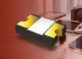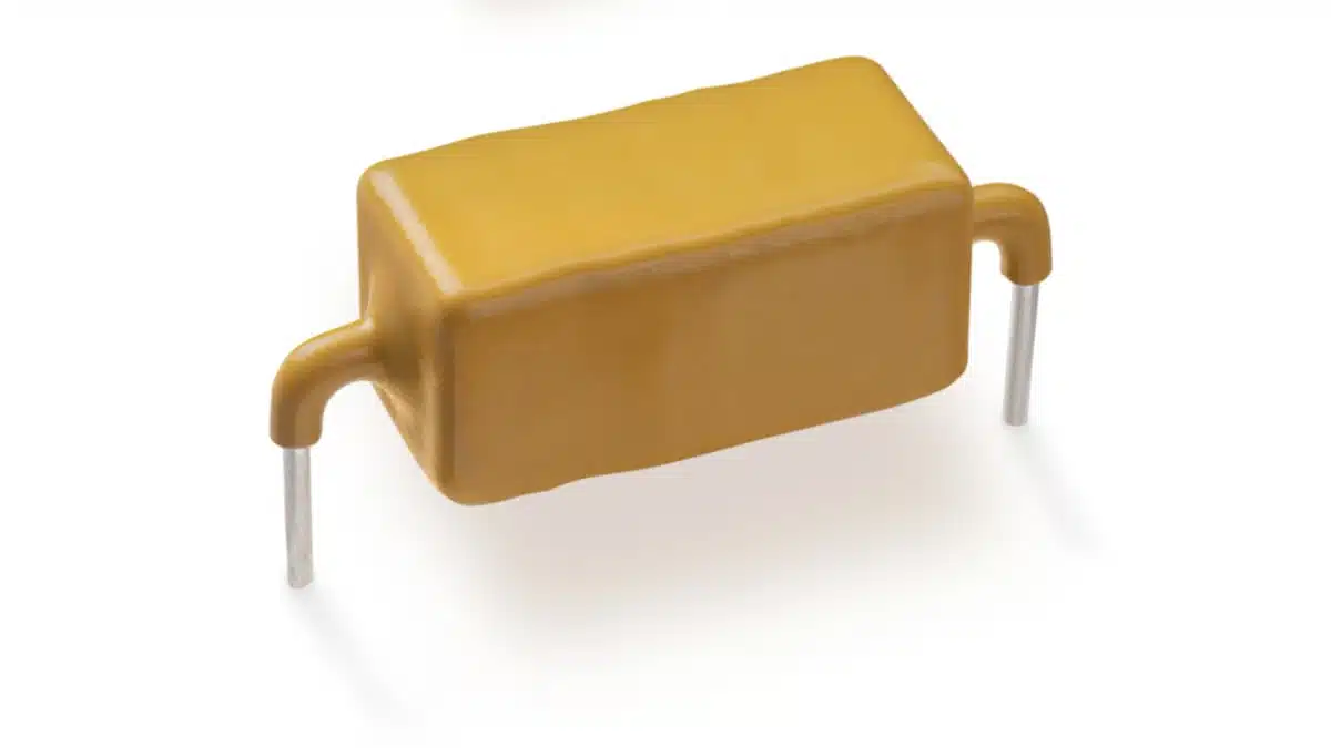
Littelfuse has introduced the AK-FL series of axial-leaded, bidirectional FlatSuppressX™ TVS diodes for high-voltage DC transient protection in aviation and eVTOL power systems.
The Littelfuse TVS Diodes three-device family combines 6 kA, 8 kA, or 10 kA 8/20 µs surge-current capability with controlled clamping levels for protecting DC rails and solid-state power controller (SSPC) circuits.
Key features and benefits
- Three high-energy TVS options: AK6-700C-FL, AK8-470C-FL, and AK10-550C-FL
- Bidirectional axial-leaded devices with a glass-passivated junction and silver-plated leads
- FlatSuppressX foldback/snapback I-V characteristic maintains clamping voltage above the working voltage but below the avalanche-voltage region
- Surge ratings of 6 kA, 8 kA, and 10 kA, specified with an 8/20 µs pulse
- Operating junction temperature range of −55 °C to +125 °C and storage temperature range of −55 °C to +150 °C
- 100% up-screening for avionics applications, including visual inspection, surge testing, temperature cycling, and high-temperature reverse-bias testing under MIL-STD-750 methods
- Lead-free reflow and wave-soldering capability, with halogen-free and RoHS-compliant construction
The new AK-FL series applies FlatSuppressX technology to higher-reliability avionics products. Its defining selection parameter is not surge-current capability alone: the maximum clamping voltage at the rated 8/20 µs peak pulse current determines the transient voltage presented to the protected semiconductor circuit.
Technical highlights
| Part number | Stand-off voltage | Maximum clamping voltage | Peak pulse current |
|---|---|---|---|
| AK6-700C-FL | 700 V | 870 V | 6 kA |
| AK8-470C-FL | 470 V | 580 V | 8 kA |
| AK10-550C-FL | 550 V | 786 V | 10 kA |
| Parameter | AK6-700C-FL | AK8-470C-FL | AK10-550C-FL |
|---|---|---|---|
| Breakdown voltage | 760 V to 825 V | 483 V to 537 V | 600 V to 663 V |
| Test current | 10 mA | 10 mA | 10 mA |
Maximum leakage at V_R | 10 µA | 10 µA | 10 µA |
| Zero-bias capacitance | 0.7 nF | 1.3 nF | 1.0 nF |
The AK6-700C-FL has a 700 V reverse stand-off rating and clamps at a maximum of 870 V at 6 kA. The AK8-470C-FL offers the lowest maximum clamp voltage, 580 V at 8 kA, while the AK10-550C-FL is rated for 10 kA and clamps at a maximum of 786 V.
All ratings use the IEC 61000-4-5-defined 8/20 µs surge waveform. The published surge response and peak-pulse derating curves should be used rather than treating the 6 kA, 8 kA, and 10 kA figures as continuous-current ratings.
Package and screening
| Package parameter | AK6-700C-FL | AK8-470C-FL | AK10-550C-FL |
|---|---|---|---|
| Overall length A | 35.65 ± 2.00 mm | 29.00 ± 2.00 mm | 35.65 ± 2.00 mm |
| Maximum body diameter D | 14.48 mm | 14.48 mm | 14.48 mm |
| Lead diameter E | 1.270 ± 0.05 mm | 1.270 ± 0.05 mm | 1.270 ± 0.05 mm |
| Packaging | 56 pieces per box | 56 pieces per box | 56 pieces per box |
The series uses an axial package, so lead spacing, lead forming, mechanical support, and creepage/clearance around the installed component need to be assessed at board level. The datasheet specifies a peak reflow temperature of 260 °C and a lead-free wave-solder peak temperature of 260 °C.
The published up-screening flow includes 100% visual inspection to MIL-STD-750 Method 2074, a one-time 100% surge test to Method 4066, 20 temperature cycles from −55 °C to +150 °C under Method 1051, and 96 hours of high-temperature reverse bias at 125 °C under Method 1038. The datasheet additionally lists environmental tests including 1,008 hours of high-temperature voltage blocking at 125 °C, 1,008 hours of biased 85 °C/85% RH testing, and temperature cycling.
Typical applications
- Aviation and eVTOL DC power rails: the 470 V, 550 V, and 700 V stand-off-voltage options address different high-voltage bus windows, while 6 kA to 10 kA 8/20 µs ratings define the stated pulse-surge capability.
- SSPC input and output protection: maximum clamping voltages of 580 V, 786 V, or 870 V must be compared with semiconductor transient withstand limits and all relevant upstream inductive overshoot.
- Aerospace and defence power distribution: the −55 °C to +125 °C junction-temperature range and published screening programme support use where component-level environmental and traceability requirements apply.
- High-reliability avionics DC rails: the bidirectional configuration supports AC or DC line-protection positions, provided the selected stand-off voltage remains above the maximum normal rail voltage.
Littelfuse identifies 270 V to 800 V DC aviation power trains, SSPC circuits, eVTOL electrical systems, and high-reliability avionics DC rail protection as target applications. The product brief presents controlled clamping as a way to reduce transient overstress and latch-up susceptibility in SSPC modules; this remains a circuit- and semiconductor-specific verification task.
Application fit
The TVS diode should be selected first by its maximum continuous stand-off voltage, then by its clamping voltage at the applicable surge current. A 700 V stand-off rating does not establish suitability for an 800 V DC rail; the complete normal-voltage envelope, tolerances, regenerative events, fault conditions, and transient profile must remain within the device’s specified operating limits.
For SSPC and semiconductor protection, place the device so that interconnect inductance does not add significant voltage overshoot between the TVS and the protected switch, controller, or power module. Protection performance must be verified under the final pulse waveform, wiring inductance, source impedance, temperature, and fault-energy conditions.
The AK-FL datasheet specifies a typical short-circuit failure mode for over-specified voltage or current. A system-level protection strategy should therefore determine the resulting fault current, available interruption method, coordination with fuses or breakers, and the consequences of a shorted TVS before release.
Design-in notes for engineers
- Select
V_Rabove the highest continuous rail voltage, including tolerance, charging conditions, regeneration, and expected operating-temperature effects. - Compare the device’s maximum clamping voltage at its specified
I_{PP}with the protected semiconductor’s transient rating, including parasitic inductive overshoot in the actual layout. - Use the datasheet pulse derating data to evaluate elevated junction-temperature conditions; the nominal 8/20 µs current rating applies at the specified test condition.
- Check the energy and pulse repetition expected in the application, not only the peak current of a single standardized surge waveform.
- Maintain short, low-inductance connections between the TVS device and the rail being protected.
- Verify axial-package mechanical retention, lead stress, creepage, clearance, insulation coordination, and soldering profile in the final assembly.
- Account for the specified short-circuit failure mode in the system fault analysis and protection-coordination plan.
- Confirm that the published screening programme, environmental tests, and any requested customer-specific screen are appropriate for the programme’s qualification requirements; component screening does not replace system-level RTCA DO-160 qualification.
Further reading
- TVS Diode: Transient Voltage Suppression Diode
- Circuit Protection Technology Dossier
- EMC and EMI Filter Design
Source
This article is based on the Littelfuse AK-FL series launch announcement and official product documentation. Engineers should consult the current manufacturer datasheet and supporting documentation for final qualification, layout, soldering, surge testing, and design-release decisions.