


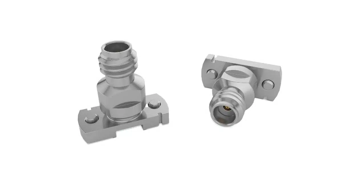
Samtec has introduced the 100-CM, a 50 Ω 1.0 mm vertical compression-mount jack for PCB-level RF and millimetre-wave test interfaces.
The solderless connector supports operation to 120 GHz, extending the available board interface for W-band and emerging D-band measurement fixtures.
Key features and benefits
- 1.0 mm precision RF jack with 50 Ω impedance
- Vertical, solderless compression-mount interface
- Specified performance to 120 GHz
- Microstrip and coplanar-waveguide transmission-line support
- PCB alignment grooves used with board fiducials
- Field-replaceable board interface without solder rework
- Threaded coupling and air-dielectric construction
- Configured part number: 100-J-P-VP-ST-CMM-1
The new 100-CM series adds a vertical compression-mount implementation to Samtec’s 1.0 mm precision RF connector offering. Its contact interface is designed to be mounted and removed mechanically rather than soldered, which can simplify repeated fixture evaluation and connector replacement.
Technical highlights
| Parameter | Value | Notes |
|---|---|---|
| Series | 100-CM | Vertical RF jack |
| Nominal impedance | 50 Ω | Precision RF interface |
| Frequency performance | DC to 120 GHz | Includes PCB launch |
| Interface size | 1.0 mm | Precision RF |
| Mounting | Solderless compression | Vertical PCB mount |
| Transmission line | Microstrip / CPW | PCB implementation |
| Board thickness | 0.016–0.125 in | Standard vertical mount |
| Board thickness with screws | 0.069–0.178 in | Screw-mounted option |
| Mounting torque | 0.5–0.8 in-lb | Board mounting |
| Centre-contact plating | 50–75 µin gold | Configured part |
The released configuration, 100-J-P-VP-ST-CMM-1, is a straight PCB jack with a compression-mount microstrip termination and no screws. It uses a 50–75 µin precision-gold centre contact and a passivated outer contact.
| Frequency range | VSWR | Test condition |
|---|---|---|
| DC to 40 GHz | 1.25:1 | Including microstrip PCB launch |
| 40 to 110 GHz | 1.4:1 | Including microstrip PCB launch |
| 110 to 120 GHz | 1.6:1 | Including microstrip PCB launch |
The published VSWR limits make the PCB launch part of the specified RF interface rather than a secondary mechanical detail. At these frequencies, launch geometry, PCB dielectric properties, copper roughness, via placement and calibration method can materially affect the measurement result.
Typical applications
The 120 GHz frequency rating, 50 Ω interface and microstrip/CPW capability support use in:
- W-band test fixtures and component-characterisation boards
- Emerging D-band laboratory test setups
- RF and microwave evaluation boards using vertical PCB launches
- High-frequency semiconductor, instrumentation and validation systems
- Cable-to-board measurement interfaces using 1.0 mm cable assemblies
Samtec identifies the 100-CM series for high-performance test applications and millimetre-wave measurement. The published frequency and VSWR data support this role, while the compression mount permits connector replacement during fixture development or maintenance.
Application fit
| Circuit or system role | Supporting published data | Check before release |
|---|---|---|
| W-band test board | 120 GHz performance | Launch and calibration |
| D-band development fixture | 110–120 GHz VSWR limit | PCB material and stack-up |
| Microstrip measurement port | Microstrip termination | Landing-pad geometry |
| CPW evaluation board | CPW compatibility | Ground continuity |
| Replaceable lab interface | Solderless compression mount | Torque and board thickness |
The alignment system uses grooves in the connector foot together with PCB fiducials to centre the alignment pin on the landing pad. This is particularly relevant for repeatable fixture assembly, but it does not eliminate the need to verify the electrical launch with the final PCB stack-up and intended calibration method.
The series mates with Samtec RF047-A cable assemblies and Nitrowave® LL095 and LL110 cable assemblies. The cable bandwidth must be selected separately: LL095 is specified to 95 GHz and LL110 to 110 GHz, so neither should be assumed to preserve a full 120 GHz measurement path.
Design-in notes for engineers
- Use the series-specific outline drawing and recommended footprint rather than a generic 1.0 mm launch.
- Maintain the specified 0.5–0.8 in-lb board-mount torque; uneven or excessive tightening can affect the mechanical interface and RF repeatability.
- Confirm the applicable board-thickness range before selecting the screwless or screw-mounted configuration.
- Place and dimension PCB fiducials to work with the connector’s alignment features.
- Validate the complete launch, transmission line, cable and calibration approach through the highest operating frequency.
- Treat the 110–120 GHz region separately during de-embedding and uncertainty analysis because the published VSWR limit changes to 1.6:1.
- Check the selected mating cable and adapters as a system; connector bandwidth alone does not define the assembled test path.
- Download the available design-qualification report, CAD model and test documentation before fixture or production release.
For broader context on flexible RF measurement interconnects, see Samtec Explains Low-Loss Coaxial Cable Construction. Practical connector selection also depends on environmental, mechanical and system-level constraints, as outlined in Six Essential Tips To Select The Right Connector.
Further reading
- Samtec Explains Low-Loss Coaxial Cable Construction
- Six Essential Tips To Select The Right Connector
- Samtec VNX+ ANSI/VITA 90: Rugged Small Form Factor Standard
Source
The information is based on the Samtec press release and official 100-CM product documentation. Engineers should consult the current manufacturer datasheet, outline drawing, qualification report and applicable test documentation before final qualification and design release.
References
- Samtec press release: Samtec 1.0 mm Connectors Capable of DC to 120 GHz
- Samtec 100-CM product page
- Samtec 1.00 mm Precision RF Connectors, 50 Ohm
- Samtec 100-CM product specification sheet
- Samtec 100-CM outline drawing and footprint
- Samtec 100-CMM design qualification test report
- Samtec solderless compression-mount RF connectors eBrochure