











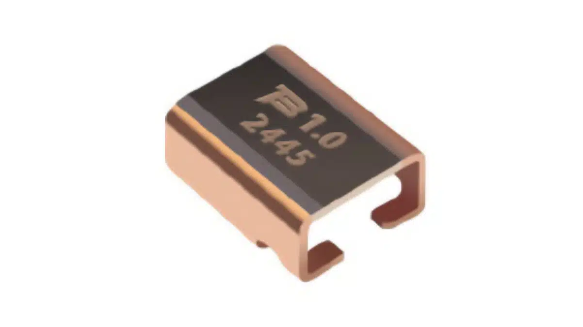
Bourns has extended its CSS4C-1216 automotive-grade four-terminal current sense resistor series with additional resistance values and a new ±3% tolerance option.
The extension broadens selection within a 0.2 mΩ to 3.0 mΩ shunt-resistor range for high-current measurement circuits in battery-management systems, power modules and industrial electronics.
Key features and benefits
- New resistance and tolerance options expand the CSS4C-1216 ordering range, including ±3% tolerance.
- The series uses an electron-beam welded metal-strip shunt with four terminals for Kelvin sensing.
- Four-terminal sensing separates the high-current path from the voltage-sense connection, helping reduce errors caused by PCB copper and solder-joint resistance.
- Low inductance below 2 nH supports current measurement where switching-edge response matters.
- The series is AEC-Q200 compliant, RoHS compliant and halogen free.
- It is offered in a 1216 case size with power ratings from 2 W to 5 W at 100 °C.
Technical highlights
| Parameter | CSS4C-1216 |
|---|---|
| Component type | Four-terminal current-sense resistor |
| Case size | 1216 |
| Resistance range | 0.2 mΩ to 3.0 mΩ |
| Power rating at 100 °C | 2 W to 5 W |
| Tolerance options | ±1%, ±3%, ±5% |
| TCR, 20 °C to 60 °C | ±50, ±100, ±150 ppm/°C |
| Operating temperature | −65 °C to +170 °C |
| Inductance | Less than 2 nH |
| Qualification | AEC-Q200 compliant |
The CSS4C-1216 combines low milliohm resistance with Kelvin terminals and a specified TCR range. Resistance tolerance determines the initial contribution to current-measurement error, while TCR determines how much the sensed value can shift over temperature.
The current Bourns product selector lists ±1%, ±3% and ±5% tolerance, a 0.2 mΩ to 3.0 mΩ resistance range, 2 W to 5 W power ratings, and TCR options of ±50, ±100 and ±150 ppm/°C. The manufacturer’s September 2026 product-extension release aligns with these values.
Typical applications
The released application scope includes current sensing in battery-management systems, power modules and industrial electronics.
- Battery-management systems: Low resistance reduces sense-voltage loss in high-current battery paths, while the −65 °C to +170 °C operating-temperature range and AEC-Q200 compliance support automotive electronic designs.
- Power modules: The 2 W to 5 W rating at 100 °C and sub-2 nH inductance support current-feedback and protection positions where thermal loading and switching transients must both be assessed.
- Industrial electronics: The 0.2 mΩ to 3.0 mΩ range permits a trade-off between lower dissipation and a larger measurable sense voltage at a given current.
For system-level selection, engineers should treat current sense resistors as both a power component and a measurement element: the resistor value, amplifier offset, ADC resolution, gain error and thermal gradient all contribute to final current accuracy.
Application fit
| Circuit position | Published supporting characteristics | Selection focus |
|---|---|---|
| Battery-current monitor | 0.2 mΩ to 3.0 mΩ, Kelvin terminals, AEC-Q200 compliance | Sense voltage and total error budget |
| Power-module current feedback | Up to 5 W at 100 °C, less than 2 nH | Pulse loading and PCB heat spreading |
| Industrial high-current monitor | −65 °C to +170 °C, ±50 ppm/°C minimum TCR option | Ambient temperature and calibration |
| Current protection path | Four-terminal connection, low milliohm range | Fault pulse and amplifier common-mode range |
AEC-Q200 is a passive-component stress-test qualification, not vehicle-level approval. Final use in an automotive ECU, inverter or charger still requires application-level validation, including the electrical environment, PCB assembly process and system reliability plan.
Design-in notes for engineers
- Select resistance from the required full-scale sense voltage, permitted insertion loss and peak current; do not select only from the nominal continuous-current value.
- Apply the 2 W to 5 W rating at the stated 100 °C reference condition and verify derating against local ambient temperature, copper area, airflow and neighbouring heat sources.
- Route the two sense traces directly from the dedicated Kelvin terminals to the current-sense amplifier inputs; avoid sharing current-carrying copper with the sense path.
- Keep the high-current loop compact and use symmetrical copper around the shunt where possible to limit thermal gradients that can add offset.
- Assess short-duration overload, start-up, inrush and fault-current conditions separately. No public CSS4C-1216 pulse-overload curve or dedicated reliability report was identified in the reviewed documentation.
- Confirm the chosen resistance value, tolerance, TCR option, land pattern, soldering profile and current datasheet revision before layout and production release.
- Check the sense-amplifier input common-mode range and transient tolerance against the actual placement of the resistor in the power path.
Further reading
- Bourns Extends Current Sense Resistors for High-Current Power Designs with 0.1 mΩ and 15 W
- Bourns Automotive Wide Terminal Current Sense Resistors
- TT Electronics Releases Precise Current Sensing 4-Terminal Shunt Resistors
Source
This article is based on the Bourns product-extension release and official CSS4C-1216 product documentation. Engineers should consult the current manufacturer datasheet and related documentation for final qualification, footprint, assembly and design-release decisions.












