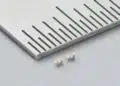
Samsung Electro-Mechanics has introduced a low-profile and embedded MLCC lineup aimed at height-constrained and high-density electronics.
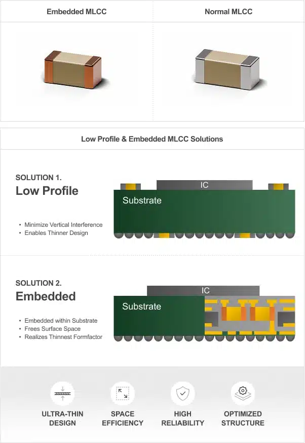
The Samsung release covers 0.5 mm-thick 0402, 05035 and 0603 MLCCs, plus an embedded 0402 option for PCB-integrated decoupling.
Key features and benefits
- Low-profile MLCCs: 0.5 mm maximum thickness is specified for six listed parts, reducing component height in compact assemblies.
- Embedded MLCC: The CL05Z226MS6B3W# is listed as a 0402 (1005 metric), 22 µF, 2.5 V, X6T part with 0.8 mm maximum thickness for PCB embedding.
- Three-terminal option: CL19A226MR5NWN# is identified as a three-terminal 05035 (1209 metric) MLCC.
- High capacitance in small cases: The announced range spans 4.7 µF to 22 µF, with voltage ratings from 2.5 V to 25 V.
- The release positions the products for compact devices including foldable smartphones, smart glasses, TWS products, high-performance chipsets and communication modules.
Technical highlights
| Part number | Case size | Capacitance | Rated voltage | TCC | Max. thickness |
|---|---|---|---|---|---|
| CL05A105MP5C64# | 0402 / 1005 | 10 µF | 10 V | X5R | 0.5 mm |
| CL05A475MP4Z64# | 0402 / 1005 | 4.7 µF | 10 V | X5R | 0.5 mm |
| CL19A226MR5NWN# | 05035 / 1209 | 22 µF | 4 V | X5R | 0.5 mm |
| CL05A156MQ4N68# | 0402 / 1005 | 15 µF | 6.3 V | X5R | 0.5 mm |
| CL10A106MO5FZN# | 0603 / 1608 | 10 µF | 16 V | X5R | 0.5 mm |
| CL10A106MA5FZN# | 0603 / 1608 | 10 µF | 25 V | X5R | 0.5 mm |
| CL05Z226MS6B3W# | 0402 / 1005 | 22 µF | 2.5 V | X6T | 0.8 mm |
The currently accessible product page for CL05A475MP4Z64# specifies a 1.00 ± 0.15 mm by 0.50 ± 0.15 mm body, 0.40 ± 0.10 mm thickness, 4.7 µF capacitance with ±20% tolerance, 10 V DC rating and X5R characteristics from −55 °C to +85 °C. It is listed in mass production.
This differs from the release table’s “0.5T max” entry for that part family. The current product-page dimensional specification is followed here for the individual orderable part.
Typical applications
The 0402 low-profile X5R parts address local MLCC decoupling where assembly height is constrained, including compact battery-powered electronics. Their 6.3 V, 10 V and 25 V ratings determine the DC rails for which they can be considered.
The 05035 three-terminal CL19A226MR5NWN# combines 22 µF capacitance, a 4 V rating and X5R dielectric in a 0.5 mm maximum-thickness part. The release identifies it as a three-terminal device but does not provide impedance, insertion-loss or terminal-configuration data; its circuit use should therefore be confirmed against the current detailed datasheet.
Samsung positions the embedded X6T MLCC for PCB-integrated mounting, where locating capacitance inside the board can free surface area and shorten the connection from the PDN to the load. The release describes this as a route to lower impedance and improved noise suppression, but no impedance curve, ESR data, embedded-process guide or reliability documentation was publicly identified in the material reviewed.
Application fit
| Circuit position | Supporting published data | Selection boundary |
|---|---|---|
| Low-voltage rail decoupling | 2.5 V to 25 V, 4.7 µF to 22 µF | Verify DC-bias capacitance |
| Thin portable assemblies | 0.5 mm maximum listed thickness | Confirm final mounted height |
| PCB-embedded decoupling | 22 µF, 2.5 V, X6T, embedded designation | Confirm lamination process |
| Three-terminal filtering | 22 µF, 4 V, X5R, three-terminal designation | Obtain impedance data |
Design-in notes for engineers
- Check the voltage rating against steady-state rail voltage, start-up overshoot, load-step excursions, fault conditions and expected derating margin before final selection.
- X5R and X6T ceramic capacitor capacitance must be evaluated at the actual DC bias, temperature and frequency; nominal capacitance alone is not sufficient for PDN design.
- The accessible CL05A475MP4Z64# page gives an X5R range of −55 °C to +85 °C. Do not apply that temperature range automatically to the other announced parts until each current part-specific datasheet is checked.
- Confirm pad geometry, solder profile, board flex stress, placement orientation and acoustic-noise requirements against the manufacturer’s current mounting guidance before layout release.
- Embedded capacitors require fabrication-process compatibility checks, including PCB stack-up, lamination pressure and temperature, via strategy, post-lamination electrical test and repair policy. This does not replace system-level validation.
- For the three-terminal part, obtain the current datasheet and frequency-domain characteristics before assigning it to a high-frequency filter or noise-suppression role.
Further reading
- MLCC Multilayer Ceramic Capacitors Technology Overview
- Ceramic Capacitor MLCC Dielectric Types and Characteristics
Source
The information is based on the Samsung Electro-Mechanics product announcement and the official documentation available for the CL05A475MP4Z64# product page. Engineers should consult the current manufacturer datasheet, product page and mounting documentation for final qualification and design release.