Passive Components Blog
No Result
View All Result
  • Home
  • News
    • All
    • Aerospace & Defence
    • Antenna
    • Applications
    • Automotive
    • Capacitors
    • Circuit Protection Devices
    • electro-mechanical news
    • Filters
    • Fuses
    • Inductors
    • Industrial
    • Integrated Passives
    • inter-connect news
    • Market & Supply Chain
    • Market Insights
    • Medical
    • Modelling and Simulation
    • New Materials & Supply
    • New Technologies
    • Non-linear Passives
    • Oscillators
    • Passive Sensors News
    • Resistors
    • RF & Microwave
    • Telecommunication
    • Weekly Digest
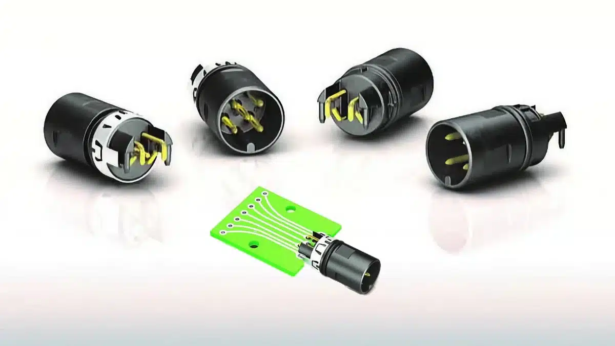
    binder angled M12-A midmount panel-mount PCB connector for centric board mounting, showing compact front-facing industrial connector geometry

    binder Adds Midmount M12-A PCB Connectors for Slim Sensors

    Bourns PST065 and PST10 Series compact incremental potentiometers with hollow shafts for rotary position feedback

    Bourns Expands Compact Incremental Potentiometer Offering

    Wk 35 Electronics Supply Chain Digest

    Samsung MLCC Revenue Seen Above KRW 8T by 2027, Murata EOL Actions Reshape Supply

    ROHM SDR01 high anti-surge thick-film chip resistor in 1005 metric 0402 package with 0.33 W rated power

    ROHM Introduces Anti-Surge 0402 Resistors Rated at 0.33 W

    ECIA Industry Pulse Q3 2026 chart showing passive components, semiconductors and electro-mechanical component market sentiment and lead-time pressure

    ECIA Industry Pulse Moderates as Passive Lead Times Tighten

    LG Innotek Demonstrates FC-BGA Substrates With Embedded Silicon Capacitors for AI Power Delivery

    On-Chip 3D-Printed Copper Microinductors: A New Route to Compact RF Electronics

    Emerging Capacitor Markets in Fusion Energy

    Trending Tags

    • Ripple Current
    • RF
    • Leakage Current
    • Tantalum vs Ceramic
    • Snubber
    • Low ESR
    • Feedthrough
    • Derating
    • Dielectric Constant
    • New Products
    • Market Reports
  • Knowledge Blog
  • Dossiers
    • AI Hardware Dossier
    • Automotive Dossier
    • Industrial Robotics Dossier
    • Power Converter Dossier
    • Capacitor Dossier
    • Resistor Dossier
    • Inductor Dossier
    • Circuit Protection Dossier
  • Suppliers
    • Who is Who
  • PCNS
    • PCNS 2025
    • PCNS 2023
    • PCNS 2021
    • PCNS 2019
    • PCNS 2017
  • Events
  • Home
  • News
    • All
    • Aerospace & Defence
    • Antenna
    • Applications
    • Automotive
    • Capacitors
    • Circuit Protection Devices
    • electro-mechanical news
    • Filters
    • Fuses
    • Inductors
    • Industrial
    • Integrated Passives
    • inter-connect news
    • Market & Supply Chain
    • Market Insights
    • Medical
    • Modelling and Simulation
    • New Materials & Supply
    • New Technologies
    • Non-linear Passives
    • Oscillators
    • Passive Sensors News
    • Resistors
    • RF & Microwave
    • Telecommunication
    • Weekly Digest
    binder angled M12-A midmount panel-mount PCB connector for centric board mounting, showing compact front-facing industrial connector geometry

    binder Adds Midmount M12-A PCB Connectors for Slim Sensors

    Bourns PST065 and PST10 Series compact incremental potentiometers with hollow shafts for rotary position feedback

    Bourns Expands Compact Incremental Potentiometer Offering

    Wk 35 Electronics Supply Chain Digest

    Samsung MLCC Revenue Seen Above KRW 8T by 2027, Murata EOL Actions Reshape Supply

    ROHM SDR01 high anti-surge thick-film chip resistor in 1005 metric 0402 package with 0.33 W rated power

    ROHM Introduces Anti-Surge 0402 Resistors Rated at 0.33 W

    ECIA Industry Pulse Q3 2026 chart showing passive components, semiconductors and electro-mechanical component market sentiment and lead-time pressure

    ECIA Industry Pulse Moderates as Passive Lead Times Tighten

    LG Innotek Demonstrates FC-BGA Substrates With Embedded Silicon Capacitors for AI Power Delivery

    On-Chip 3D-Printed Copper Microinductors: A New Route to Compact RF Electronics

    Emerging Capacitor Markets in Fusion Energy

    Trending Tags

    • Ripple Current
    • RF
    • Leakage Current
    • Tantalum vs Ceramic
    • Snubber
    • Low ESR
    • Feedthrough
    • Derating
    • Dielectric Constant
    • New Products
    • Market Reports
  • Knowledge Blog
  • Dossiers
    • AI Hardware Dossier
    • Automotive Dossier
    • Industrial Robotics Dossier
    • Power Converter Dossier
    • Capacitor Dossier
    • Resistor Dossier
    • Inductor Dossier
    • Circuit Protection Dossier
  • Suppliers
    • Who is Who
  • PCNS
    • PCNS 2025
    • PCNS 2023
    • PCNS 2021
    • PCNS 2019
    • PCNS 2017
  • Events
No Result
View All Result
Passive Components Blog
No Result
View All Result

binder Adds Midmount M12-A PCB Connectors for Slim Sensors

15.9.2026
Reading Time: 6 mins read
A A
binder angled M12-A midmount panel-mount PCB connector for centric board mounting, showing compact front-facing industrial connector geometry

binder has expanded its M12 portfolio with angled M12-A panel-mount connectors for centric PCB mounting.

The new midmount arrangement places the PCB edge within the connector geometry, allowing the connector axis to lie in the plane of the circuit board rather than above it.

RelatedPosts

binder Prints Electronics on 3D Components Connector Surface

Binder Hybrid Connector Simplifies One Cable Automation

binder Releases Tool‑Tightenable M12 Connectors for Improved Reliability

This approach targets devices in which a standardized M12 interface must be integrated into a narrow cylindrical or otherwise space-constrained enclosure. The THR version is intended for reflow processing on an SMT line.

Key features and benefits

  • Midmount PCB geometry: The connector receives the PCB at its front edge, avoiding the stacked height associated with a connector mounted on top of the board.
  • Centric interface placement: In a cylindrical housing, the connector axis can align with the housing axis, helping preserve the usable cross-section for PCB components.
  • M12 A-coded interface: The new panel-mount connectors use the M12 A-coded interface specified in DIN EN 61076-2-101 and are available with four or five contacts.
  • Automated assembly option: The THR termination is reflow-solderable and includes an integrated pick-up surface for pick-and-place handling.
  • Configuration choices: binder states that shielded and unshielded versions are offered, with or without an O-ring.
  • Environmental sealing: The stated protection rating is IP68 when the connector is mated and locked. The complete connector, mating counterpart, assembly process, and housing sealing concept must be assessed for the final equipment design.

Technical highlights

ParameterManufacturer-stated information
Connector styleAngled, front-mounted panel-mount connector for centric PCB mounting
InterfaceM12 A-coded, DIN EN 61076-2-101
Contact count4-pin and 5-pin versions
PCB thickness1 to 2 mm
TerminationTHR, reflow-solderable
ShieldingShielded or unshielded versions
Sealing optionWith or without O-ring
Protection ratingIP68 when mated and locked
Rated voltage60 V
Rated impulse withstand voltage1,500 V
Operating temperature-40 °C to +85 °C
Mechanical durabilityMore than 100 mating cycles
Contact finishGold-plated contacts
Contact-body materialLCP, UL 94 V-0

The manufacturer states that the connector’s PCB mounting concept reduces the installation-height penalty of a conventional surface-mounted arrangement. This is a mechanical-integration benefit rather than a published electrical-performance comparison with previous connector versions.

The 60 V rated voltage and 1,500 V rated impulse withstand voltage are selection parameters, not a substitute for an application-specific insulation and transient assessment. Engineers should evaluate steady-state voltage, switching transients, surge environment, pollution degree, creepage and clearance distances, and the properties of the fully assembled equipment.

Application fit

binder identifies sensor and peripheral equipment with restricted installation space as the primary use case. Examples include level, distance and pressure sensors; light barriers; position switches; measuring transducers in cylindrical housings; and compact fieldbus or peripheral devices.

System constraintRelevance of the midmount design
Narrow tubular housingKeeps the M12 interface centered while avoiding connector height above the PCB
Automated PCB assemblyTHR termination enables the connector to pass through a reflow process with the PCB assembly
Standardized sensor interfaceRetains an M12 A-coded external interface for compatible applications
PCB thickness between 1 and 2 mmThe PCB must be specified within the stated mechanical mounting range
Outdoor or washdown exposureIP68 performance must be validated for the mated connector and finished product enclosure

For industrial sensor equipment, centric placement can simplify the mechanical relationship between the front connector interface, the enclosure axis and a narrow electronics assembly. It may also remove a manual wire-soldering operation used with straight-contact panel connectors and separate internal wiring.

Design-in notes for engineers

  • Confirm the exact variant. Verify contact count, shielding configuration, O-ring option, mating connector and applicable product documentation before freezing the schematic or mechanical design.
  • Check the PCB edge geometry. The manufacturer specifies a 1 to 2 mm PCB thickness range; the current outline drawing and land-pattern information should control board-edge dimensions, plated-hole details, component keep-outs and tolerances.
  • Qualify the THR reflow process. Validate the recommended solder paste, stencil, thermal profile, board support, placement accuracy and solder-joint inspection criteria with the current manufacturer documentation.
  • Evaluate mechanical loading. Mating and unmating forces, cable routing, connector torque, enclosure fixation and any vibration or shock exposure should be assessed at system level. Do not assume that a stated mating-cycle figure validates the connector for a specific duty cycle.
  • Treat IP68 as an assembled-interface rating. Confirm the required mating condition, locking arrangement, seals, cable assembly and enclosure interfaces. The manufacturer’s announcement does not specify the test conditions for the IP68 claim; confirm them in the current datasheet.
  • Review EMC requirements. For shielded versions, validate the shield termination path, continuity through the mating pair, cable shield design and enclosure bonding. Shielding effectiveness depends on the complete interconnect and system layout.
  • Check electrical margins. Confirm current capability, contact resistance, conductor size, temperature rise and required derating in the current datasheet. The announcement does not state a rated current.
  • Validate the final product. Perform assembly, environmental, sealing, vibration, EMC and functional testing under the final operating conditions. Connector qualification does not replace system-level validation.

For a broader overview of the coding choices used in industrial circular interfaces, see the M12 connector coding technical overview.

Further reading

  • Circular Connectors Coding
  • binder Offers Wide Range of M12 Panel Mount Connectors
  • New binder Panel Mount Connectors Offer More Precise Transmission
  • binder Releases Tool-Tightenable M12 Connectors

Source

This article is based on the binder manufacturer press release announcing angled M12-A panel-mount connectors for centric PCB mounting. Engineers should consult the current manufacturer datasheet, PCB layout information, outline drawing and applicable documentation for final component qualification and design release.

References

  1. binder press release: Midmount instead of surface-mounted: binder expands the M12 portfolio with angled PCB connectors
  2. binder M12-A automation connector product family

Related

Recent Posts

Hirose FH51 automotive FPC/FFC connector with low-profile receptacle construction and top-and-bottom contact arrangement

Hirose Automotive FPC/FFC Connector Adds One-Action Mating up to 125°C

8.9.2026
4

Connector Industry Performance Accelerates Through Mid-2026

31.8.2026
52

Molex Presents MiniMix Hybrid Power and Signal Connectors for Compact Humanoid Joints

6.8.2026
132

Molex Unveils Automotive Ethernet Connectors for Next‑Gen SDV Architectures

2.7.2026
95

binder Prints Electronics on 3D Components Connector Surface

1.7.2026
65

EMC‑Compliant PCB and Connector Design Guidelines

22.6.2026
246

Hirose Releases Ultra‑low Profile FPC‑to‑board Connector

17.6.2026
116

Molex Expanded AirBorn SInergy Hybrid Connectors with 25 A Power Modules

16.6.2026
98

Hirose Releases 0.5 mm Floating Board-to-Board Connector for EV Powertrain Designs

15.6.2026
68

Upcoming Events

Sep 16
17:00 - 18:00 CEST

Designing a 5 kW, 800 V-to-50 V PSFB Converter for Next-Generation Data Centers

Sep 29
16:00 - 17:00 CEST

Cybersecurity 2026

Nov 24
16:00 - 17:00 CET

Component selection with the WE REDEXPERT® DC-DC Converter Designer Tool

View Calendar

Popular Posts

  • Buck Converter Design and Calculation

    0 shares
    Share 0 Tweet 0
  • LLC Resonant Converter Design and Calculation

    0 shares
    Share 0 Tweet 0
  • Boost Converter Design and Calculation

    0 shares
    Share 0 Tweet 0
  • Flyback Converter Design and Calculation

    0 shares
    Share 0 Tweet 0
  • Earthing Systems and IEC Classification Explained

    0 shares
    Share 0 Tweet 0
  • MLCC and Ceramic Capacitors

    0 shares
    Share 0 Tweet 0
  • Resistor Symbols

    0 shares
    Share 0 Tweet 0
  • Capacitor Charging and Discharging

    0 shares
    Share 0 Tweet 0
  • Audio Capacitors: Choosing Capacitors for Crossover Circuits

    0 shares
    Share 0 Tweet 0
  • Capacitor Symbols

    0 shares
    Share 0 Tweet 0

Newsletter Subscription


Passive Components Blog

© 2015–2026
All rights reserved

  • Home
  • Privacy Policy
  • EPCI Membership & Advertisement
  • About

No Result
View All Result
  • Home
  • Knowledge Blog
  • Dossiers
  • PCNS

© 2015–2026
All rights reserved