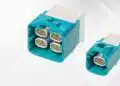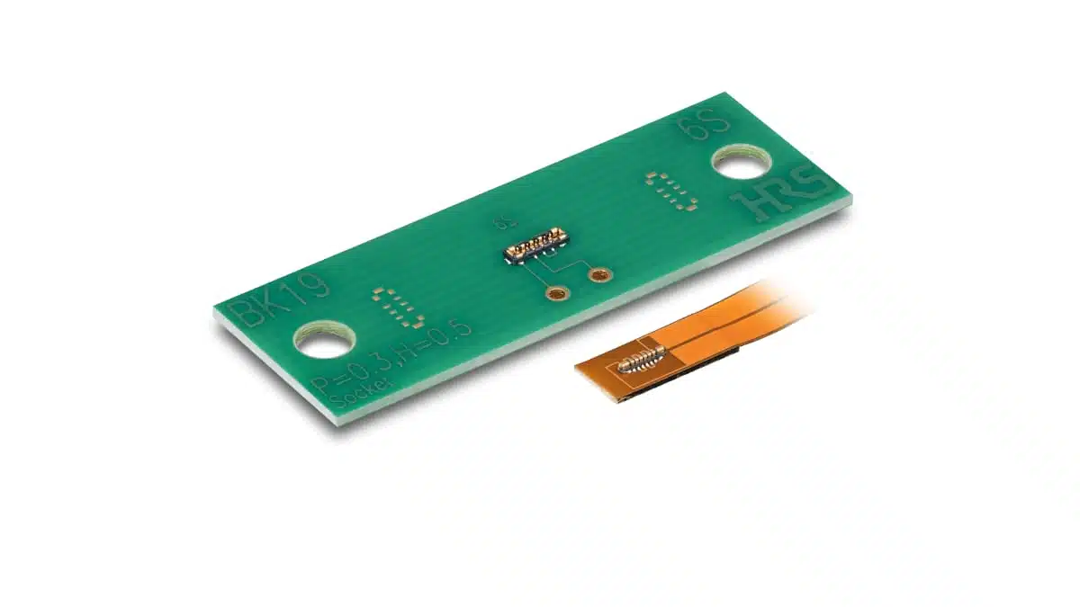
Hirose’s new BK19 series is an ultra‑miniature single‑row FPC‑to‑board connector that combines signal and power in one interface for space‑constrained mobile and wearable designs.
It targets applications where every fraction of a millimeter in height and width matters, while still requiring robust mechanical reliability in daily use.
Key features and benefits
- Ultra‑low profile and narrow width
0.3 mm pitch, approximately 1.2 mm connector width and 0.5 mm stacking height enable very tight z‑height budgets in smartphones, smartwatches and other ultra‑slim portable devices. These dimensions give mechanical designers more freedom to allocate volume to batteries, cameras or sensors instead of connectors. - Hybrid signal + power in a single row
Single‑row configuration with six signal positions and two power positions allows both low‑level interfaces and power rail connection through one compact component, reducing connector count and routing complexity on dense boards. - Fully armored housing for mechanical robustness
The connector features a fully armored design intended to protect the insulating housing from chipping and cracking during handling, rework or drop events. This is particularly relevant for thin end devices that may experience flexing and mechanical shocks. - Dimpled contact lock for high extraction force
A dimpled contact lock structure increases extraction force, helping to maintain a secure connection under vibration, bending and repeated user handling. This supports reliability targets in mobile and wearable products that are frequently moved or worn on the body. - Wide self‑alignment range for easier assembly
Generous self‑alignment in both pitch and width directions (±0.3 mm each, according to the manufacturer) improves mating tolerance in automated assembly and manual rework. This helps mitigate the usual assembly challenges associated with very small FPC‑to‑board connectors. - Insert‑molded plug and receptacle to prevent solder wicking
Insert‑molded construction of both plug and receptacle is intended to block solder wicking into the contact area during reflow. This supports stable electrical performance and reduces assembly defects for high‑volume production.
Typical applications
According to Hirose, the BK19 series is designed for compact, highly integrated consumer and portable equipment where connector footprint and height are strongly constrained.
Typical use cases include:
- Smartphones and feature phones, especially in display, camera, button and sensor interconnects where mating height directly impacts device thickness.
- Wearable devices such as smartwatches and fitness trackers that demand minimal profile and robust resistance against daily mechanical stress.
- VR and AR glasses where internal space for electronics and cabling is extremely limited and weight needs to be minimized.
- Portable gaming devices, handheld consoles and accessories where hybrid power/signal connectors can simplify the internal harness and PCB layout.
- Compact medical devices, including portable monitors and diagnostic tools, where small, reliable interconnects are needed and board real estate is at a premium.
In many of these applications, the FPC‑to‑board connector is used to bridge mechanical hinges, curved housings or stacked board configurations, making both low profile and self‑alignment important for manufacturability.
Technical highlights
The BK19 series focuses on miniaturization in all three dimensions while retaining mechanical robustness. Key structural and dimensional points from the manufacturer include:
- Single‑row structure with 6 signal contacts and 2 power contacts.
- Target use as an FPC‑to‑board interface with hybrid power and signal functionality.
- Nominal contact pitch of 0.3 mm.
- Connector body width of approximately 1.2 mm.
- Mated stacking height of approximately 0.5 mm.
- Metal mold covers at both ends of the connector to assist alignment and protect the housing.
- Fully armored design around the housing.
- Self‑alignment tolerance in pitch and width directions of approximately ±0.3 mm.
- Insert‑molded plug and receptacle structure designed to suppress solder wicking during reflow.
For detailed electrical characteristics such as rated current per contact, voltage rating, contact resistance, insulation resistance and operating temperature range, designers should refer to the official BK19 series datasheet. These parameters are critical when using the power contacts to carry system rails or battery connections in compact consumer devices.
Dimensional overview
The following table summarizes the main mechanical parameters as described in the press information; always verify final values in the current datasheet before design‑in:
| Parameter | Typical value / description |
|---|---|
| Contact pitch | 0.3 mm |
| Configuration | Single row, 6 signal + 2 power |
| Connector width | Approx. 1.2 mm |
| Stacking height (mated) | Approx. 0.5 mm |
| Self‑alignment (pitch dir.) | Approx. ±0.3 mm |
| Self‑alignment (width dir.) | Approx. ±0.3 mm |
Design‑in notes for engineers
- Check electrical ratings early
Before assigning the BK19 power positions to battery or system rails, confirm the maximum rated current and voltage per contact in the datasheet, including any derating curves over temperature. This will determine whether the connector can carry continuous loads, transient peaks or only low‑power auxiliary rails. - Use the hybrid structure to reduce connector count
Combining power and signal in one row can simplify flexible cable routing and reduce the number of connectors in the system. When doing so, maintain appropriate creepage and clearance on the FPC and main board layout, especially if the power contacts carry higher voltages. - Leverage self‑alignment for assembly robustness
The relatively wide self‑alignment window is helpful for automated pick‑and‑place and for FPC insertion in final assembly. Ensure that the recommended land pattern, board stiffeners and FPC reinforcement are followed so that the connector can fully self‑align without mechanical obstruction. - Account for 0.5 mm stacking height in mechanical stack‑ups
In very thin devices, small tolerances in plastic parts and display modules can consume much of the mechanical budget. Include the BK19 stacking height, FPC thickness and any stiffeners in the mechanical stack‑up analysis to avoid interference or unwanted stress on the connector. - Protect the connector in high‑stress regions
While the housing is fully armored, additional mechanical design measures such as local ribs, shielding cans or bracket support may be beneficial if the connector is located near a hinge, edge or area subject to bending. The goal is to allow the connector to absorb normal handling loads but avoid concentrated stress from enclosure deformation. - Follow soldering and reflow recommendations
Insert‑molded construction helps prevent solder wicking, but correct stencil design, solder volume and reflow profiles remain essential. Use the land pattern and reflow guidance provided by the manufacturer, and verify joint quality with X‑ray or cross‑sections during initial process qualification. - Plan for potential future variants
Since larger pin‑count versions are under development, it may be useful to reserve some PCB and housing space in platform‑type designs. This can ease migration from an 8‑position connector to a higher pin‑count BK19 variant in next‑generation product revisions.
Source
This article is based on information from the official Hirose Electric press release for the BK19 series and related product documentation published by the manufacturer.