











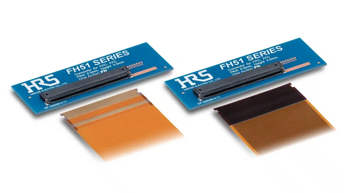
Hirose Electric has released the FH51 series, a 0.5 mm-pitch FPC/FFC receptacle for automotive display interconnects.
The series combines a 1.98 mm height, top-and-bottom contact arrangement, and one-action locking structure; Hirose specifies heat resistance to 125°C when used with FPC, while the stated limit is 105°C with FFC. The initial mass-production version has 60 positions, with further position counts planned.
What changed
- Hirose has introduced the FH51 as a new automotive FPC/FFC connector series.
- The current production listing identifies a 60-position receptacle, FH51-60S-0.5SH.
- The announced design uses a one-action lock rather than a separate actuator operation during mating.
- The top-and-bottom contact configuration permits FPC/FFC routing without selecting the connector by contact orientation.
- Hirose states that 10, 30, 40, 50, and 80-position versions are planned; these should not be treated as released production options until their individual product documentation is available.
- The manufacturer identifies automotive displays, cluster panels, and LiDAR among the intended applications.
Key technical data
| Parameter | Manufacturer-stated value | Engineering relevance |
|---|---|---|
| Series | FH51 | Automotive FPC/FFC connector family |
| Current listed production part | FH51-60S-0.5SH | 60-position receptacle currently listed by Hirose |
| Contact pitch | 0.5 mm | Sets FPC/FFC conductor pitch and PCB land-pattern requirements |
| Connector height | 1.98 mm | Relevant to display-stack and enclosure clearance |
| Contact arrangement | Top and bottom contacts | Allows cable routing without dependence on contact orientation |
| Mating structure | One-action lock | Removes the need for separate actuator operation during insertion |
| Heat resistance with FPC | 125°C | Verify against the final FPC construction and local temperature |
| Heat resistance with FFC | 105°C | A different limit applies when FFC is used |
| Position range | 60 positions in mass production; 10, 30, 40, 50, and 80 planned | Confirm availability and documentation for each position count |
| Major applications named | Automotive displays, cluster panels, LiDAR | Application fit still depends on the final electrical and mechanical requirements |
The manufacturer’s public series page lists one 60-position receptacle. It does not, in the information reviewed here, establish contact resistance, voltage rating, current rating, insulation resistance, dielectric-withstanding voltage, retention force, vibration performance, mating-cycle rating, or specific qualification status. Confirm these parameters in the current part-specific datasheet and drawing before design release.
Engineering implications
For display modules, the top-and-bottom contact configuration can simplify cable routing where the FPC or FFC must approach the PCB from a constrained direction. This is a mechanical and assembly benefit, but the selected cable type remains critical because Hirose specifies different heat-resistance limits for FPC and FFC.
The one-action structure can reduce the space otherwise needed to operate a separate connector actuator. For design engineers, this may help in tightly packaged display assemblies, but it also makes the approved insertion direction, cable stiffener geometry, insertion depth, and mating-force limits essential production controls.
A 0.5 mm pitch and 60 contacts make PCB footprint accuracy, solder-mask definition, coplanarity, and contamination control particularly important. The manufacturer’s announcement does not publish the high-speed electrical characteristics of the interconnect; signal-integrity requirements, impedance control, crosstalk, and channel loss therefore need to be assessed from current technical documentation and in the final display-link implementation.
The stated 125°C capability applies when using FPC, not automatically when using FFC. Engineers should evaluate the connector, cable, stiffener, adhesive system, nearby heat sources, and enclosure thermal profile as one assembly. This does not replace system-level validation.
Application fit
| Application or design requirement | Why the product may fit | What to verify |
|---|---|---|
| Automotive display module | Hirose identifies automotive displays as a target application; the series supports high contact counts in a low-profile form factor | Display-link electrical requirements, cable routing, thermal exposure, vibration, and connector retention |
| Cluster panel | The 1.98 mm connector height and one-action mating can support constrained mechanical assemblies | Clearance above the connector, assembly access, FPC bend radius, and end-product qualification requirements |
| LiDAR module | Hirose lists LiDAR as an application example | Actual signal type, channel performance, environmental conditions, cable selection, and mechanical loading |
| Automated assembly | Hirose states that the one-action lock is suited to robotic assembly | Pick-and-place process, insertion force, alignment tolerance, vision inspection, and mating verification |
Verification checklist
- Confirm that the selected cable is FPC or FFC, then apply the corresponding manufacturer-stated temperature limit: 125°C for FPC or 105°C for FFC.
- Obtain the current specification sheet for the exact part number and verify voltage, current, contact resistance, insulation resistance, dielectric-withstanding voltage, and mating-cycle ratings.
- Use the current Hirose 2D drawing and recommended land pattern for pad geometry, solder-mask design, PCB thickness, and placement tolerances.
- Verify the cable conductor pitch, thickness, stiffener dimensions, contact orientation, insertion depth, and allowable bend radius against the part-specific documentation.
- Check the full assembly temperature profile, including display backlight heat, processor or power-device proximity, enclosure conditions, and soldering exposure.
- Validate retention, contact continuity, and mechanical loading under the final vibration, shock, cable-routing, and service conditions.
- Assess the complete signal channel for impedance discontinuities, crosstalk, insertion loss, and EMC performance where high-speed display or sensor links are used.
- Confirm that the released 60-position part is the required configuration; do not specify planned position counts until their current datasheets and production status are available.
Further reading
- Single Pair Ethernet for Humanoid Robot In-Robot Networks
- August 2026 Interconnect, Passives and Electromechanical Components Market Insights
Source
This article is based on Hirose Electric’s FH51 series press release and official product-series documentation. Engineers should consult the current manufacturer datasheet, 2D drawing, 3D model, qualification documentation, and application information for final component selection, validation, and design release.












