











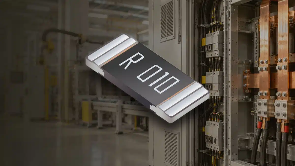
Bourns has introduced the CRH2512 series of metal-alloy current-sense resistors for compact, high-current surface-mount designs.
The new 2512 family combines resistance values from 0.5 mΩ to 30 mΩ with a maximum 5 W rating, targeting current measurement where conduction loss, thermal rise and measurement stability must be balanced.
Key features and benefits
- 2512 surface-mount metal-alloy resistor series for low-ohmic current sensing
- Resistance range from 0.5 mΩ to 30 mΩ
- Maximum rated power of 5 W
- Resistance tolerances of ±1%, ±2% and ±5%
- Operating temperature range of −55 °C to +170 °C
- TCR of ±75 ppm/°C at 0.5 mΩ and ±50 ppm/°C from 1 mΩ to 30 mΩ
- Maximum working current up to 100 A, subject to resistance value and terminal-temperature limit
- Matte tin-plated, RoHS-compliant terminations and Moisture Sensitivity Level 1 classification
The series extends Bourns’ current-sense resistor portfolio with a 5 W option in a 2512 footprint. The announcement positions the range for high-current industrial and power-management circuits, while the publicly available product page currently contains unit errors for resistance values; the press release gives the credible range in milliohms, but final selection should be checked against the current CRH2512 datasheet before release.
Technical highlights
| Parameter | CRH2512 specification | Selection relevance |
|---|---|---|
| Package | 2512 surface mount | PCB area and thermal path |
| Resistance range | 0.5 mΩ – 30 mΩ | Sense voltage and loss |
| Rated power | Up to 5 W | Self-heating margin |
| Tolerance | ±1%, ±2%, ±5% | Initial current accuracy |
| TCR at 0.5 mΩ | ±75 ppm/°C | Temperature-related error |
| TCR at 1–30 mΩ | ±50 ppm/°C | Temperature-related error |
| Operating temperature | −55 °C to +170 °C | Ambient and hot-spot limit |
| Maximum working current | Up to 100 A | Value-dependent limit |
| Maximum overload current | Up to 200 A | Short-duration fault check |
The current limit varies with resistance value. The 0.5 mΩ part is specified for 100 A maximum working current and 200 A maximum overload current; 1 mΩ to 3 mΩ versions are limited to 70.71 A and 141.42 A, respectively, while 4 mΩ to 30 mΩ versions are limited to 35.35 A and 70.71 A.
Rated current also follows the relationship , but must never exceed the specified working-current limit. The terminal-temperature limits are 105 °C for 0.5 mΩ to 3 mΩ and 85 °C for 4 mΩ to 30 mΩ, making PCB copper area, airflow and neighbouring heat sources central to the usable power rating.
Typical applications
The specified low resistance, 5 W rating and current capability support current shunts in:
- Switching power supplies and high-current DC/DC converters, where low resistance reduces dissipation in the monitored rail
- Battery-management circuits, where the 0.5 mΩ option and 100 A working-current limit support monitoring of high-current charge and discharge paths
- Industrial controllers and motor-control stages, where the −55 °C to +170 °C operating range and low TCR help limit temperature-related measurement drift
- Digital power and energy meters, where tolerance and TCR affect calibration and measurement stability
- Overcurrent monitoring and protection circuits, where overload-current capability must be assessed against the actual fault waveform and pulse duration
A current-sense resistor is installed in series with the monitored path, creating a proportional voltage drop for a current-sense amplifier or ADC. Lower resistance reduces voltage drop and dissipation, but also reduces the available signal amplitude; amplifier offset, noise and common-mode range therefore become more significant.
Application fit
| Circuit position | Supporting ratings | Primary check |
|---|---|---|
| Battery current shunt | 0.5 mΩ, 100 A working current | Pulse and fault energy |
| DC/DC converter sensing | 1–30 mΩ, 5 W maximum | Loss and thermal margin |
| Motor-drive phase sensing | −55 °C to +170 °C, low TCR | Transient overload profile |
| Industrial power monitor | ±1% to ±5% tolerance | Required accuracy budget |
| Digital meter input | ±50 ppm/°C TCR at 1–30 mΩ | Temperature calibration |
The 0.5 mΩ version creates a 50 mV nominal sense voltage at 100 A and dissipates 5 W at that current. By contrast, a 30 mΩ device reaches its 35.35 A maximum working-current rating well below a 5 W calculation, so the value-specific current restriction remains decisive.
Design-in notes for engineers
- Select resistance from the required sense voltage, amplifier input range, allowable insertion loss and accuracy budget rather than power rating alone.
- Calculate steady-state dissipation at maximum continuous current, then assess the actual terminal temperature with the intended copper pattern, layer stack-up, airflow and nearby heat sources.
- Respect both the calculated mit and the value-specific maximum working-current limit.
- Evaluate inrush, short-circuit and repetitive-pulse conditions separately from continuous dissipation; a maximum overload-current figure alone does not define permitted pulse duration or energy.
- Route Kelvin sense traces directly to the resistor terminals and away from the high-current copper path where measurement accuracy is important. Two-terminal milliohm shunts can otherwise accumulate solder-joint and PCB-trace resistance in the measurement path.
- Include initial tolerance, TCR, shunt self-heating, amplifier offset and ADC error in the end-to-end current-measurement budget.
- Check the actual reflow profile, land pattern and assembly documentation before layout release. No CRH2512-specific public outline drawing, land pattern, soldering guideline, qualification report, SPICE model, impedance curve or reliability report was found in the available engineering-file directory.
Further reading
- Current Sense Resistors: Principles and Application Considerations
- Current Sensing Resistors in Power Electronics
- Power Resistors: Technology and Applications
Source
This article is based on the Bourns CRH2512 launch announcement and official product documentation. Engineers should consult the current manufacturer datasheet and associated documentation for final qualification, land-pattern definition, thermal validation and production release.












