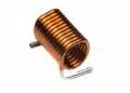
A trans-inductor voltage regulator (TLVR) is a multiphase buck-converter architecture that uses coupled magnetic components and an auxiliary current path to increase the rate at which output current can rise after a load step.
It is relevant to low-voltage, high-current point-of-load regulators for processors, FPGAs, ASICs and similar loads where transient current demand can change extremely quickly.
This article also examines a current-dependent ballast-inductor approach that can keep auxiliary-path ripple lower during normal operation while providing additional transient-current support after a fast load step.
Key Takeaways
- The TLVR multiphase buck converter improves transient response using coupled inductors and auxiliary paths, ideal for high-current applications.
- Conventional synchronous buck converters face limitations in current slew rate due to inductance and voltage constraints.
- By interleaving phases and adding magnetic coupling, TLVR enables faster output current changes under load steps.
- Simulation results demonstrate significant output current enhancements compared to traditional designs.
- Typical applications of TLVR include CPUs, GPUs, FPGAs, and high-performance power rails in servers and data centers.
- A current-dependent ballast inductor can reduce normal-operation ripple while providing higher auxiliary-path current during a load transient.
Why TLVR matters
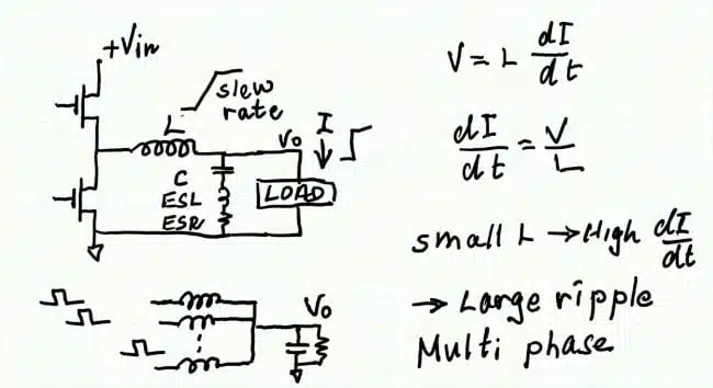
A conventional synchronous buck converter responds to a positive load step by increasing inductor current. The attainable current slew rate is constrained by the voltage across the inductor and its inductance:
Reducing inductance increases the available current slew rate, but it also raises inductor ripple current and can increase output-voltage ripple. The resulting output-capacitor requirement can become substantial.
Interleaving several buck phases improves the ripple situation because phase currents are time-shifted. In the four-phase example discussed in the video, the output-current ripple frequency becomes four times the individual switching frequency. Interleaved multiphase PWM converters therefore provide a useful baseline for understanding why TLVR is attractive.
TLVR adds magnetic coupling between phases and an auxiliary, or ballast, inductor path. Its purpose is not simply to parallel inductors, but to use coupled-winding current components to reinforce the output-current response during a transient.
Operating principle
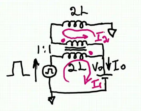
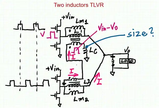
The presentation builds the TLVR concept in stages. It begins with a single inductor, then replaces it with two parallel inductors, each having twice the inductance. With the same applied voltage pulse, current in each branch is halved, while their combined output current remains unchanged.
The energy stored in an inductor follows:
For the two-inductor example, each inductor has twice the original inductance but half the peak current. The video therefore shows that each branch stores half the energy of the original inductor. This illustrates why magnetic-component size is influenced by current and stored energy, rather than inductance value alone.
The next step adds a one-to-one secondary winding to one branch and connects the second inductor through that winding. The transformer can be represented by an ideal transformer, magnetising inductance and—outside the simplified model—leakage inductance. This arrangement introduces an auxiliary current contribution that reaches the output in addition to the principal phase current.
In the simplified one-phase arrangement, the presentation finds that the output current is approximately 1.5 times the input-side current. This is a circuit-level current relationship in the idealised example, not an efficiency gain or a universal multiplication factor for every practical TLVR implementation.
From coupling to multiphase TLVR
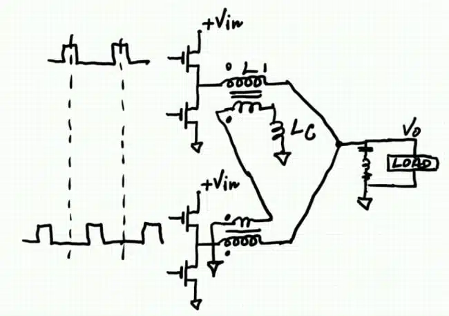
A multiphase TLVR uses a coupled inductor for each buck phase. Secondary windings are connected in series with an auxiliary ballast inductor, while the primary windings remain part of their respective buck phases.
When a switching pulse excites one phase, it produces the normal phase current and also drives current through the coupled auxiliary path. The coupling transfers a current contribution into the other phases’ magnetic network and toward the output. The load therefore receives the direct contribution of the active phase plus contributions created through the trans-inductor structure.
The key benefit is a larger aggregate output-current change for a given correction pulse. In a normal multiphase buck converter, the controller can extend the on-time of one or more phases after detecting a load step. In the TLVR arrangement, the coupled network helps distribute the transient response across the phase system.
Simulation examples
The video uses LTspice simulations to illustrate the operating mechanism. The following values are simulation inputs or reported waveform observations, not component-selection requirements.
| Simulation case | Conditions stated in the video | Reported observation |
|---|---|---|
| Simplified two-phase case | 3 microsecond pulse; 150 nH inductors | Output current approaches 600 A in the simulation |
| Four-phase TLVR | Four interleaved phases; 150 nH inductance; 300 kHz switching frequency; 0.1 duty cycle; 100 A load; 1 mF output capacitor; open-loop operation | 56 A peak-to-peak aggregate current waveform versus 32 A for the indicated phase current; ratio approximately 1.75 |
| Four-phase output | 12 V input and 0.1 duty cycle | Average output approximately 1.2 V; reported output ripple approximately 7 mV |
| Correction-pulse case | One phase receives a simulated extra 1 microsecond pulse | Output-current increase approximately 254 A and slew rate approximately 260 A per microsecond |
For the four-phase example, the 300 kHz phase switching frequency produces an output-current ripple frequency of about 1.2 MHz. Higher ripple frequency can reduce the capacitance needed for a given ripple-voltage target, although real designs must also consider capacitor ESR, ESL, mounting inductance and the physical placement of capacitors around the load.
The video identifies the simulations as simplified. They do not include all parasitic effects, so the reported currents and ripple values should be treated as explanatory results rather than hardware performance predictions.
Correction-pulse response
The final example considers a regulator operating at steady state when the output voltage falls after a load step. The controller response is modelled by extending the pulse of one operating phase.
The simulated extended pulse causes a sharp increase in the excited-phase current and produces a response in neighbouring phases through the coupled magnetic network. The total output current includes the directly excited phase and the contributions from the remaining phases.
The waveform contains oscillation because the example operates open loop. This behaviour should not be interpreted as the response of a complete closed-loop regulator, where feedback would adjust subsequent pulses. Loop compensation, current sensing, delay, PWM resolution and the placement of output capacitors remain decisive factors in a hardware design.
Optimising TLVR with a Current-Dependent Ballast Inductor
The ballast inductor is a key component in the TLVR auxiliary path. Its value affects both the current available during a load transient and the current ripple that flows in the secondary-winding loop during normal operation.
A low fixed ballast inductance allows auxiliary current to rise quickly when the controller extends a switching pulse after a load step. This can improve the total output-current slew rate and reduce output-voltage droop. However, the same low inductance also causes higher circulating-current ripple during normal operation. Higher ripple can increase RMS current, winding loss, core loss and stress on the coupled magnetic assembly.
A high fixed ballast inductance has the opposite effect. It reduces auxiliary-path ripple in steady operation, but also restricts the additional current that can flow during a transient. The designer must therefore balance normal-operation loss against fast transient response.
A current-dependent ballast inductor offers a possible way to improve this compromise. The intended behaviour is high inductance at ordinary ballast-path current and lower inductance only when a load transient drives the current above a chosen threshold.
At low current, the higher inductance suppresses normal ripple. During a fast transient, the current rises above the transition level, the effective inductance decreases and the auxiliary path can contribute current more rapidly to the output.
The desired characteristic can be expressed conceptually as:
where is the ballast inductance and is the ballast-inductor current.
In a practical magnetic component, this transition is gradual rather than an ideal step. The objective is not uncontrolled saturation. The objective is a controlled, repeatable inductance-versus-current characteristic that remains predictable across temperature, switching conditions and production tolerance.
Fixed and Current-Dependent Inductance
A fixed-inductance ballast component must always operate as a compromise. It can be selected for lower ripple or for stronger transient current support, but not independently for both conditions.
A current-dependent ballast inductor provides two operating regions. Its higher inductance is used during normal operation, while its lower inductance becomes effective when the transient event requires faster current rise.
The following table summarises the principle.
| Ballast-inductor profile | Normal-operation behaviour | Load-transient behaviour | Main consequence |
|---|---|---|---|
| Low fixed inductance | Higher auxiliary-path current ripple | Strong auxiliary-current contribution | Good transient response, but potentially higher RMS current and loss |
| High fixed inductance | Lower circulating-current ripple | Lower auxiliary-current contribution | Better steady-state behaviour, but weaker transient response |
| Current-dependent inductance | High inductance can limit normal ripple | Lower inductance can support a faster transient current rise | Potentially combines lower ripple with stronger transient response |
The current-dependent concept can be explored in LTspice using a behavioural inductor model in which inductance is defined as a function of current. This approach is useful for comparing possible characteristics before developing a practical magnetic component.
The video Sam Ben-Yaakov, “Optimizing the TLVR Performance by a Current-Dependent Inductor” uses illustrative LTspice examples with a four-phase TLVR. It compares a constant ballast inductance with cases where inductance remains high at low current and then falls at a selected current threshold. A later transition can retain a waveform close to the constant-inductance case before the event, while providing a stronger current rise after the transient begins. A lower transition threshold can create still higher transient current, but it may also affect normal operating ripple.
Simulation Interpretation
The purpose of the simulation is to show the principle rather than define a production-ready design. In the illustrated examples, reducing ballast inductance when the transient current rises enables a higher auxiliary-path current and a higher aggregate output-current response.
A late inductance transition is generally the most attractive target. It keeps the ballast inductor in its higher-inductance state during normal current ripple, then allows the inductance to fall only when the correction pulse drives a real transient event.
An early transition can produce a larger output-current increase. However, it can also reduce ballast inductance during ordinary switching cycles. This can increase circulating-current ripple, RMS current and power loss, reducing the benefit of the approach.
| Inductance profile | Before transient | During correction pulse | Practical interpretation |
|---|---|---|---|
| Constant inductance | Stable baseline ripple | Baseline output-current rise | Reference case |
| Later L(I) transition | Similar to high-inductance baseline | Higher current after threshold is crossed | Preferred balance in many cases |
| Earlier L(I) transition | May affect normal ripple | Highest potential current rise | Requires careful loss and control evaluation |
The simulated current waveforms should not be treated as hardware specifications. Practical results depend on coupling coefficient, winding resistance, AC resistance, leakage inductance, capacitor ESR and ESL, PCB resistance and inductance, core loss, magnetic temperature and closed-loop controller behaviour.
Magnetic Implementation
Every practical inductor changes inductance to some degree with DC bias. The challenge is to produce an inductance reduction that occurs at the intended current level and remains predictable over temperature and manufacturing variation.
Possible magnetic approaches include gapped ferrite cores, powder-core inductors and engineered variable-gap structures. A controlled-gap design can include a local region with reduced magnetic cross section. This region reaches saturation first as current rises, increasing the effective magnetic reluctance and reducing inductance.
The useful result is not a sudden uncontrolled collapse of inductance. A suitable component should have a defined transition range, acceptable peak-current capability and manageable core and winding losses.Design-in notes for engineers
- Define the transient target first. Establish allowable voltage deviation, load-step magnitude, current-slew demand and recovery time before selecting phase count or inductance.
- Treat the coupled inductor as a system component. Magnetising inductance, leakage inductance, winding ratio, coupling consistency and the ballast-inductor value all affect transient-current sharing.
- Check saturation margin under the full event envelope. Include steady-state DC current, ripple current, startup, current-limit events, load steps and temperature. Power inductors and storage chokes explains why saturation-current ratings must be interpreted together with inductance drop and temperature conditions.
- Minimise DCR and AC winding loss. The auxiliary path and multiple windings add copper-loss and proximity-effect considerations. Inductance, impedance, Q factor and DCR losses provides useful background on DC resistance and frequency-dependent loss mechanisms.
- Control leakage inductance deliberately. The presentation omits leakage inductance from its introductory model, but practical coupling and leakage will influence current sharing, resonant behaviour and EMI.
- Validate the full output network. Use realistic capacitor models, including ESR, ESL and PCB interconnect inductance, particularly for sub-milliohm and sub-nanohenry load-distribution paths.
- Close the loop in simulation and hardware. Verify compensation, current balancing, pulse extension limits, switching overlap, fault behaviour and response to phase tolerances.
- Characterise magnetic loss at operating conditions. Core loss, winding AC loss and temperature rise should be measured across the actual switching frequency, ripple flux, DC bias and cooling conditions. Core magnetic materials, permeability and their losses explains the dependence of magnetic properties on these conditions.
- Define the required inductance-versus-current profile. Specify high-current and low-current inductance, transition current, transition slope, temperature shift and acceptable production tolerance.
- Avoid uncontrolled saturation. The intended inductance reduction must remain predictable during maximum load, elevated temperature, startup, current-limit events and load transients.
- Verify the control loop in both inductance regions. The power-stage behaviour changes when ballast inductance falls, so stability, pulse extension, phase-current sharing and current-limit response must be verified across the complete L(I) range.
- Measure RMS and peak current separately. A current-dependent inductor may improve a short transient event but can increase circulating RMS current if its transition threshold is too low.
- Characterise magnetics under realistic excitation. Measure inductance, loss and temperature rise versus DC bias, switching frequency and ripple-flux amplitude, not only with a small-signal inductance meter.
Limits and trade-offs
TLVR can improve transient response, but it replaces a comparatively straightforward multiphase buck magnetics design with a coupled system that must be engineered as an integrated assembly. Matching between windings and phases, parasitics, magnetic saturation behaviour and layout symmetry become more important.
The topology can also introduce additional design variables. The ballast inductor and secondary-winding connection influence both transient response and circulating current. A result that appears favourable in an ideal simulation may shift once winding resistance, AC resistance, leakage inductance, capacitor parasitics, PCB resistance and controller dynamics are included.
At higher duty cycles, phase pulses can overlap. The presentation shows a four-phase example at duty cycle 0.3, where overlap occurs because four individual duty intervals cannot remain fully separated within one switching period. The topology remains operational in the example, but its detailed behaviour differs from the low-duty-cycle case and requires dedicated verification.
Typical applications
TLVR is intended for low-output-voltage, high-current power rails where a conventional multiphase buck stage faces demanding load transients. Typical targets include:
- CPU, GPU and AI-accelerator core rails
- FPGA, ASIC and high-performance SoC supplies
- High-current server and data-centre point-of-load regulators
- Telecommunications and networking processors
- Other digitally controlled loads that require rapid current delivery at low voltage
The strongest case is generally a rail where load-step performance, distributed low-inductance decoupling and power density matter more than minimum magnetic complexity.
Conclusion
TLVR extends the transient capability of a multiphase buck regulator by using coupled inductors, series-connected secondary windings and a ballast-inductor branch to create a faster aggregate output-current response. Rather than relying only on the current ramp of the directly driven phase, the coupled magnetic structure allows additional current contributions through the auxiliary path.
The ballast inductor is central to the resulting design trade-off. A low fixed inductance can improve transient current slew rate, but it also increases circulating-current ripple, RMS current and magnetic loss during normal operation. A high fixed inductance reduces ripple, but limits the auxiliary-path current available during a fast load step.
A current-dependent ballast inductor can provide a controlled compromise. It can maintain higher inductance during normal operation to limit ripple, then reduce inductance as transient current exceeds a defined threshold. This can increase auxiliary-path current and improve the output-current ramp when the load requires it.
The approach requires controlled magnetic design, realistic loss and parasitic modelling, and closed-loop verification. The coupled inductors, ballast-inductor L(I) characteristic, controller, output-capacitor network and PCB layout must be designed as one integrated high-current power-delivery system.
FAQ
TLVR stands for trans-inductor voltage regulator. The article explain an example of a topology used to generate low voltage at high current and to improve fast current rise during demanding load transients.
When the load current steps up quickly, the regulator must increase inductor current fast enough to limit output-voltage droop. Lowering inductance can improve current slew rate, but it also increases ripple current and can require more output capacitance.
TLVR uses coupled windings and an auxiliary ballast-inductor path so that a correction pulse contributes more total output current than a simple phase current ramp alone.
In the simplified explanation, the ballast inductor forms part of the auxiliary branch connected through the series secondary windings.
The ballast inductor controls current in the auxiliary secondary-winding path. Its inductance affects both circulating-current ripple during normal operation and the additional current available during a load transient.
It is a ballast inductor designed to provide relatively high inductance at low current and lower inductance after its current exceeds a selected threshold. This can reduce normal ripple while increasing transient current support.
Not necessarily. The intention is a controlled and repeatable inductance-versus-current characteristic. Uncontrolled saturation can cause excessive current, loss, temperature rise and unpredictable converter behaviour.
The higher effective output ripple frequency in a multiphase arrangement can help reduce the required output capacitance.
- TLVR Multiphase Buck Trans-Inductor Voltage Regulator Explained
- Interleaved Multiphase PWM Converters Explained
- Addressing Core Loss in Coupled Inductors
- Coupled Inductors in Multiphase Boost Converters
Source
This article adapts technical explanations and LTspice examples presented by Sam Ben-Yaakov. The original material explains how a multiphase buck TLVR uses coupled magnetic paths and a ballast-inductor branch to achieve a faster aggregate current response and explains a current-dependent ballast-inductor approach for TLVR optimisation. The video examples are intended to demonstrate the operating principle. Reported waveforms and numerical values are illustrative simulation observations, not hardware design specifications.
References
- Sam Ben-Yaakov, “Deciphering the mystery of TLVR”
- Sam Ben-Yaakov, “An intuitive explanation of the multiphase Buck Trans-Inductor Voltage Regulator”
- Sam Ben-Yaakov, “Optimizing the TLVR Performance by a Current-Dependent Inductor”