











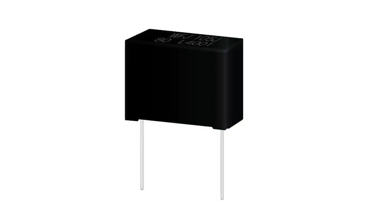
Panasonic Industry has introduced the ECWFJ series of metallized polypropylene film capacitors for cost-sensitive industrial and automotive power-electronics designs.
The Panasonic AEC-Q200-qualified range film capacitors combines 600 VDC to 1,100 VDC ratings with humidity resistance, a -40 °C to +110 °C operating range, and capacitance values from 1 µF to 12 µF.
Key features and benefits
The ECWFJ series is designed for applications where a film capacitor must maintain dependable electrical behaviour in humid and thermally demanding environments without moving to a higher-cost component class.
- Metallized polypropylene film dielectric, a commonly selected construction for low-loss capacitor duty in high-voltage DC and power-conversion circuits
- DC voltage ratings from 600 VDC to 1,100 VDC
- Capacitance range from 1 µF to 12 µF
- AEC-Q200 qualification for automotive passive-component applications
- Operating temperature range from -40 °C to +110 °C; the 1,000 V version is specified up to +105 °C
- Stable operation reported under 40 °C and 95% relative humidity for up to 1,000 hours
- Thermal-shock capability from -55 °C to +85 °C for 1,000 cycles
- Maximum ambient temperature of up to +125 °C for limited periods, according to the manufacturer
- Patterned metallization with an integrated fuse mechanism intended to support capacitance stability and fault containment over component life
- Flame-retardant plastic case and non-conductive resin construction
- RoHS compliant, with a construction intended to support UL and other applicable regulatory requirements
Technical highlights
Metallized polypropylene capacitors are valued in power electronics for their low dielectric losses and good high-frequency performance compared with many alternative dielectric technologies. In the ECWFJ family, the patterned metallization also provides a self-healing-related protection approach: a local dielectric breakdown can be isolated by the metallization pattern rather than becoming an immediate permanent short circuit.
| Parameter | ECWFJ series information |
|---|---|
| Dielectric / construction | Metallized polypropylene film capacitor |
| Rated DC voltage | 600 VDC to 1,100 VDC |
| Capacitance range | 1 µF to 12 µF |
| Operating temperature | -40 °C to +110 °C |
| 1,000 V variant temperature rating | Up to +105 °C |
| Humidity test condition | 40 °C, 95% RH, up to 1,000 hours |
| Thermal shock condition | -55 °C to +85 °C, 1,000 cycles |
| Automotive qualification | AEC-Q200 |
| Environmental compliance | RoHS |
The announced ratings position the ECWFJ series for DC-link support, snubber-related energy handling, filtering, and other high-voltage DC functions. Exact ripple-current, ESR, pulse, insulation-resistance, package-dimension, lead-spacing, and endurance specifications should be confirmed for the selected ordering code in the manufacturer datasheet.
Typical applications
Panasonic identifies the series for both automotive electrification and industrial power-conversion equipment.
- DC/DC converters in electric mobility systems
- On-board chargers
- Electric compressors
- Solar inverters
- EV charging infrastructure
- Industrial power supplies
- LED lighting power stages
- Smart meters
- Embedded power systems
For a DC-link application, the relevant selection process should begin with the maximum steady-state bus voltage, expected voltage overshoot, capacitor RMS ripple current, switching-frequency spectrum, and local thermal environment. The nominal DC rating alone is not sufficient to establish suitability, particularly in converter topologies with repetitive transient stress.
Application fit
| Application | Potential ECWFJ role | Selection priority |
|---|---|---|
| EV DC/DC converter | DC-side filtering or energy buffering | Bus voltage, ripple current, thermal cycling |
| On-board charger | High-voltage filtering and converter support | Operating temperature, humidity, safety spacing |
| Solar inverter | DC-bus support and switching-noise control | Voltage derating, lifetime at elevated temperature |
| EV charging equipment | DC filtering in power-conversion stages | Transient margin, enclosure temperature |
| Industrial power supply | Input or intermediate DC-link filtering | Ripple-current capability, PCB mechanical layout |
| LED driver or smart meter | DC filtering in compact embedded power supplies | Available board area, temperature, lifetime requirement |
Design-in notes for engineers
- Apply voltage derating: Select the rated voltage with margin for nominal bus voltage, startup conditions, regenerative events, resonant overshoot, and abnormal operating states.
- Verify ripple-current limits: Film capacitor temperature rise depends on RMS current, ESR, switching frequency, cooling conditions, PCB copper area, and nearby heat sources. Use the part-specific datasheet rather than estimating from capacitance alone.
- Assess capacitance under end-of-life conditions: The required minimum effective capacitance should include design tolerance, expected capacitance change over life, temperature effects, and any reduction caused by self-healing activity.
- Use the humidity data in context: The stated 40 °C/95% RH result is relevant for products exposed to humid atmospheres, but it does not replace an assessment of condensation risk, contamination, pollution degree, enclosure design, and possible leakage-current paths on the PCB.
- Check the thermal profile: A +110 °C operating rating can be useful in compact equipment, but the 1,000 V version has a lower stated operating limit of +105 °C. Confirm the rating for the exact voltage variant before finalising the thermal design.
- Review mechanical integration: Film capacitors can experience lead and case stress during board assembly, potting, vibration, and thermal cycling. Confirm dimensions, mounting clearances, lead configuration, and any recommended assembly restrictions from the component documentation.
- Confirm compliance at system level: AEC-Q200 qualification supports automotive component screening expectations, but system qualification still requires application-specific electrical, mechanical, environmental, and safety validation.
Source
This article is based on Panasonic Industry Europe’s product announcement for the ECWFJ metallized polypropylene film capacitor series, published on 17 August 2026. Technical values stated here reflect the manufacturer’s release; engineers should use the current manufacturer documentation for final component qualification and design release.












