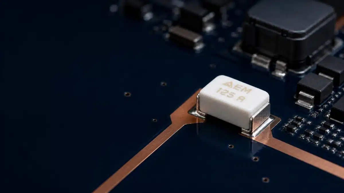
AEM Components has introduced its CMF High-Power Fuse family for high-current circuit protection in compact electronic assemblies.
The surface-mount fuses combine a 2822 package format with current ratings from 20 A to 125 A, while 150 A and 200 A options are also available according to AEM.
Key features and benefits
- High-current SMD format: The CMF series uses a 2822 package, offering a route to integrate substantial overcurrent protection directly onto a PCB rather than relying solely on a larger, board-external fuse solution.
- Rated-current coverage: AEM identifies standard options from 20 A to 125 A, plus 150 A and 200 A versions for higher-current protection requirements.
- Automotive qualification: The series is stated to be qualified to AEC-Q200 Rev. E and produced within an IATF 16949-certified quality-management environment, relevant to automotive electronic-component sourcing and qualification processes.
- Low resistance focus: AEM highlights low ESR and safe power density. In practice, low series resistance can reduce conduction loss and self-heating in a continuously loaded protection path.
- Arc suppression: The manufacturer also specifies arc-suppression characteristics, an important feature when a fuse must safely clear a fault current without sustaining an arc across the opening element.
A fuse is a one-time overcurrent protection device that interrupts the circuit when excessive current causes its fusible element to open. For wider context on protection functions and component categories, see this overview of circuit protection component types.
Technical highlights
| Parameter | Manufacturer-stated information |
|---|---|
| Product family | AEM Components CMF High-Power Fuses |
| Package | 2822 |
| Rated-current range | 20 A to 125 A |
| Additional current options | 150 A and 200 A |
| Qualification | AEC-Q200 Rev. E qualified |
| Quality-system statement | IATF 16949 certified |
| Key performance claims | Low ESR, safe power density, arc suppression |
AEC-Q200 is a stress-test qualification specification for passive components used in automotive electronics. It is useful evidence in a component-selection process, but engineering teams should still verify the exact test conditions, product-specific qualification status, operating limits, and required customer acceptance criteria for the intended design; the standard itself does not make all components automatically interchangeable. For background, see MIL Spec MIL-PRF vs Automotive AEC-Q200 Explained.
AEM’s announcement does not provide voltage rating, interrupting rating, time-current characteristic, , resistance values, derating curves, temperature limits, or detailed mechanical dimensions. These parameters should therefore be confirmed from the current manufacturer datasheet before specifying a CMF part number.
Typical applications
CMF high-power fuses may suit PCB-level overcurrent protection locations where continuous current, available fault current, board area, thermal performance, and automotive qualification requirements all need to be evaluated together.
Potential application areas include:
- Automotive ECUs, power-distribution modules, battery-management electronics, and auxiliary power branches
- DC/DC converters, onboard chargers, and inverter control electronics
- Industrial drives, power supplies, robotics, and automated-equipment control boards
- Battery-powered equipment and high-current DC distribution paths
- Commercial power-electronics assemblies that need compact circuit protection
The appropriate application depends on the complete electrical coordination of the fuse with the source, load, conductor system, switching devices, and upstream/downstream protective devices. A fuse intended for overload protection may not necessarily provide the response or interruption capability required for semiconductor protection during severe short-circuit events.
Application fit
| Design situation | Why the CMF family may be relevant | What must be verified |
|---|---|---|
| Compact high-current PCB assembly | The 2822 surface-mount format may support board-level protection integration | Copper area, terminal temperature, resistance, and assembly process |
| Automotive electronic module | AEC-Q200 Rev. E qualification supports automotive passive-component screening expectations | Exact qualified part number, PPAP requirements, temperature range, and customer-specific requirements |
| DC power branch | Low resistance can help limit normal operating losses | Voltage rating, prospective short-circuit current, interrupting rating, and coordination |
| Repetitive high-current load | Safe power-density positioning may be relevant where board space is constrained | Current derating, pulse loading, inrush withstand, and thermal cycling |
Design-in notes for engineers
- Start with the fault case, not only nominal current. Establish normal current, maximum continuous current, overload profile, inrush current, prospective fault current, and the maximum system voltage before selecting a fuse rating.
- Check time-current behaviour. The fuse must tolerate legitimate start-up or charging pulses while clearing a damaging overload or fault within the allowable energy limit of the protected circuit.
- Verify interruption capability. A rated current alone does not establish whether a device can safely interrupt the available fault current at the actual DC or AC voltage.
- Calculate thermal conditions on the real PCB. High-current surface-mount protection parts depend strongly on copper spreading, pad geometry, layer stack-up, airflow, nearby heat sources, and terminal temperatures.
- Treat low ESR as a thermal-design input. Conduction loss rises with the square of current, , so small resistance differences can become important at tens or hundreds of amperes.
- Review coordination with adjacent protection. Confirm whether the CMF fuse must coordinate with a battery fuse, contactor, transient suppressor, power switch, cable protection, or another branch fuse.
- Use current manufacturer documentation for release. Validate the selected part number against the datasheet, qualification documentation, recommended footprint, reflow profile, and applicable derating guidance.
For a practical checklist covering rated voltage, continuous and inrush current, environmental conditions, and available fault current, see Fuse Selection Guidelines.
Further reading
- Circuit Protection Component Types
- Fuse Selection Guidelines
- An Overview of Electrical and Electronic Fuse Markets and Technologies
- Primary Fuse Protection Against Overvoltage Events
Source
This article is based on the AEM Components press release on CMF High-Power Fuses. Engineers should consult the current manufacturer datasheet and supporting documentation for final component qualification, protection coordination, and design release.