











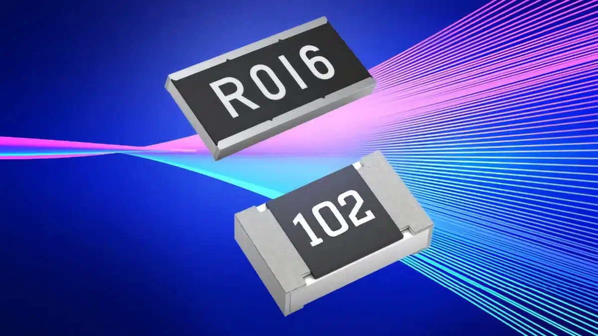
Panasonic Industry has positioned its thick-film current sense resistor portfolio as an alternative to conventional metal shunt resistors in selected low- and medium-current applications.
The approach targets designs that need low resistance, controlled temperature behaviour and robust thermal performance, while potentially reducing component cost and easing footprint migration.
Key features and benefits
- Resistance values are available down to 10 mΩ in selected Panasonic thick-film current sense resistor series.
- Selected series offer temperature coefficient of resistance values as low as ±75 ppm/°C, helping to limit temperature-related measurement drift.
- Wide-terminal and double-sided resistive-element structures are used in parts of the portfolio to improve heat dissipation and lower operating temperature.
- Soft termination technology is intended to reduce solder-joint stress during thermal cycling, supporting board-level reliability.
- Panasonic estimates potential component-cost savings of up to 50% versus selected comparable metal shunt solutions, although the actual result depends on resistance value, power requirement, qualification needs, sourcing volume and application conditions.
- Footprint-compatible options are available in selected case sizes, which can simplify migration where the electrical and thermal operating range overlaps with a metal-shunt solution.
Where thick film fits
Metal shunt resistors remain the usual choice where a design requires extremely low resistance, very high pulse capability, exceptionally high power dissipation or the lowest possible TCR across a demanding temperature range. Thick-film current sense resistors become more attractive when those extreme requirements are not necessary.
For low- and medium-current sensing, a thick-film resistor device can provide a practical compromise between resistance value, power handling, temperature stability, PCB area and bill-of-material cost. The key is to assess the full operating condition rather than selecting solely on nominal resistance.
Technical highlights
Current sensing is based on measuring the voltage developed across a known resistance:
Lower resistance reduces insertion loss and self-heating, but also produces a smaller sense voltage that must be resolved accurately by the current-sense amplifier or controller. A low TCR helps keep the relationship between current and measured voltage more stable as the resistor temperature changes.
| Parameter | Panasonic thick-film portfolio position |
|---|---|
| Minimum stated resistance | Down to 10 mΩ in selected series |
| Lowest stated TCR | As low as ±75 ppm/°C in selected series |
| Thermal design features | Wide terminals and double-sided resistive structures in selected designs |
| Board-level reliability feature | Soft termination technology in relevant series |
| Migration approach | Selected footprint-compatible case sizes |
| Target range | Selected low- and medium-current sensing applications |
Exact power ratings, pulse-load capability, tolerance, package size, rated temperature range and qualification status must be confirmed for the individual series and part number in the relevant manufacturer datasheet.
Typical applications
Panasonic identifies the resistor portfolio for applications where current monitoring supports efficiency, protection and control functions, including:
- AI server and other high-density power infrastructure
- Battery management systems
- DC/DC converters and power supplies
- Industrial robotics
- Motor-control electronics
- Industrial automation equipment
- Protection and monitoring circuits in power-conversion stages
In AI infrastructure and server power supplies, current sense resistors can be used to monitor converter stages, load sharing and protection thresholds. In battery systems, they can support charge/discharge current measurement, overcurrent protection and state-estimation functions when the required accuracy is aligned with the resistor’s temperature performance.
Design-in notes for engineers
- Check the real resistance range: A 10 mΩ resistor may suit a higher-current rail, but the resulting sense voltage must still meet amplifier offset, noise and ADC-resolution requirements.
- Calculate continuous dissipation: Use the worst-case RMS or DC current and include derating for ambient temperature, copper area and airflow. The resistor’s terminal and PCB temperatures may differ substantially from ambient.
- Review TCR across the full temperature range: A low nominal resistance can change measurably through self-heating and environmental temperature variation. Use the applicable TCR specification for the chosen series, not the best value stated for the broader portfolio.
- Evaluate Kelvin routing: Route separate sense traces from the resistor terminals to the measurement circuit where accuracy matters. This reduces error caused by high-current copper trace resistance and voltage drop.
- Assess pulse and surge conditions: Motor starts, hot-plug events, converter faults and battery transients can create short-duration stress that is not represented by the continuous power rating.
- Consider terminal geometry and solder joints: Wide-terminal parts can improve thermal coupling to the PCB, but the land pattern, solder volume and copper layout should follow the manufacturer recommendation.
- Validate replacement claims at system level: Mechanical footprint compatibility alone is not sufficient for a metal-shunt replacement. Confirm resistance tolerance, TCR, power derating, thermal rise, overload behaviour and long-term stability in the intended circuit.
- Use production-specific costing: The stated savings potential is an estimate. Compare qualified component prices, sourcing conditions, approval effort and any PCB-layout changes for the actual production volume.
Source
This article is based on a Panasonic Industry Europe product notice published on 13 August 2026. Performance values and suitability statements refer to selected thick-film current sense resistor series; final component selection should be verified against the current manufacturer datasheet and the application’s electrical and thermal requirements.












