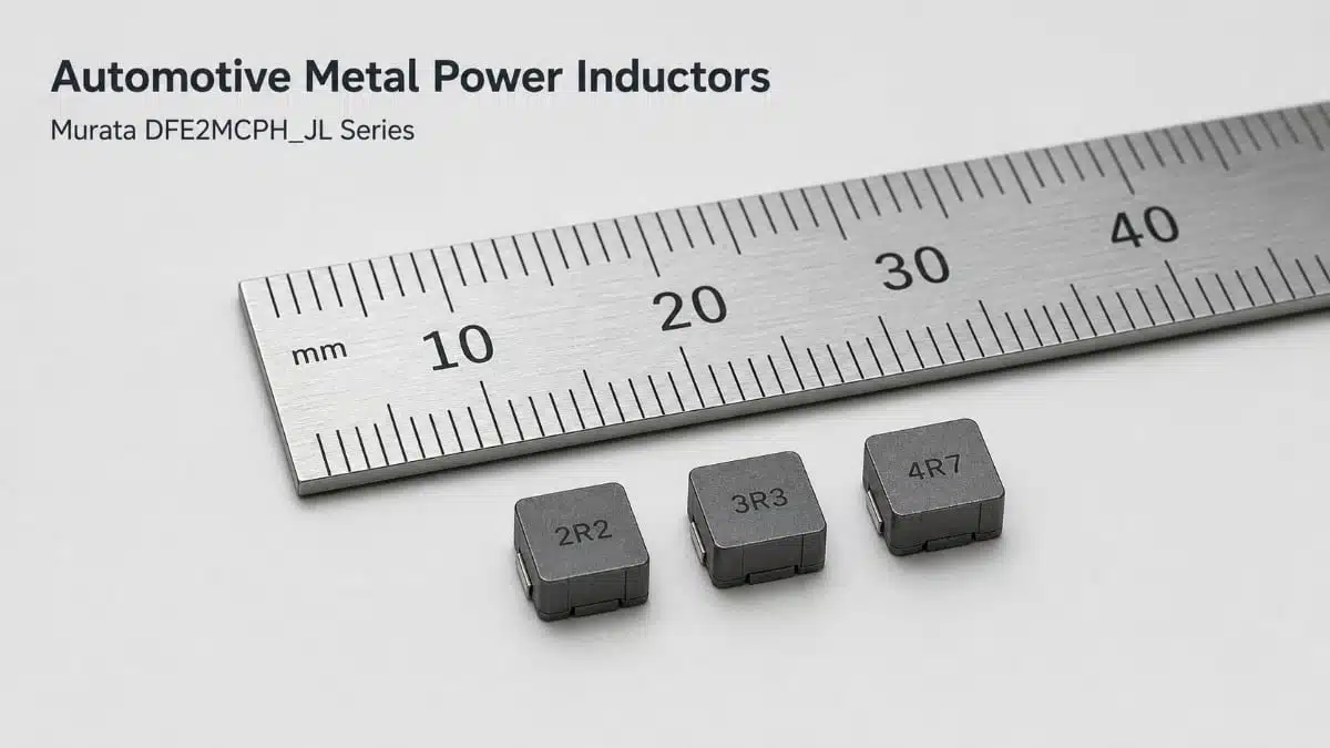
Murata has expanded its DFE2MCPH_JL family of automotive-grade metal power inductors with nine new inductance values from 0.10 µH to 4.7 µH.
This Murata power inductor additions extend the selection range for compact automotive DC-DC power stages in ADAS, IVI and other vehicle electronic systems, while retaining the series’ 0806-inch footprint, 40 V withstand voltage and AEC-Q200 qualification.
Key features and benefits
- Eleven inductance options: The DFE2MCPH_JL family now spans 0.10 µH to 4.7 µH, including nine newly introduced values; this gives power-supply designers more latitude to trade current ripple, transient response and current capability.
- Compact 0806-inch package: The 2.0 mm × 1.6 mm footprint supports dense point-of-load regulators and distributed power rails in space-constrained ECUs and infotainment hardware.
- Automotive qualification: The series is compliant with AEC-Q200, the stress-test qualification standard commonly applied to passive components intended for automotive electronic applications.
- 40 V withstand voltage: This characteristic supports use on regulated low-voltage power rails and converter stages, subject to verification of the complete operating and transient-voltage conditions in the final circuit.
- Low DC resistance and high current capability: Lower DCR helps limit conduction loss and self-heating, especially where a compact converter inductor carries substantial DC load current.
- Metal power-inductor construction: Metal composite and moulded inductor technologies are widely used where compact size, current handling and mechanical robustness are priorities in automotive power electronics; see the technical background on metal composite inductors.
Technical highlights
Murata specifies the new DFE2MCPH_JL options with ±20% inductance tolerance. The published ratings include a current based on inductance change and a separate current based on temperature rise; both must be considered during component selection.
| Status | Part number | Inductance | DCR, max. | Current based on inductance change, max. | Current based on temperature rise, max. |
|---|---|---|---|---|---|
| New | DFE2MCPHR10MJLLQ | 0.10 µH | 10 mΩ | 11.1 A | 7.5 A |
| New | DFE2MCPHR15MJLLQ | 0.15 µH | 12 mΩ | 8.4 A | 6.5 A |
| New | DFE2MCPHR22MJLLQ | 0.22 µH | 15 mΩ | 8.2 A | 5.6 A |
| Existing | DFE2MCPHR33MJLLQ | 0.33 µH | 18 mΩ | 6.9 A | 5.1 A |
| Existing | DFE2MCPHR47MJLLQ | 0.47 µH | 22 mΩ | 5.4 A | 4.4 A |
| New | DFE2MCPHR68MJLLQ | 0.68 µH | 40 mΩ | 4.4 A | 3.4 A |
| New | DFE2MCPH1R0MJLLQ | 1.0 µH | 48 mΩ | 3.9 A | 2.9 A |
| New | DFE2MCPH1R5MJLLQ | 1.5 µH | 80 mΩ | 3.1 A | 2.3 A |
| New | DFE2MCPH2R2MJLLQ | 2.2 µH | 120 mΩ | 2.6 A | 1.8 A |
| New | DFE2MCPH3R3MJLLQ | 3.3 µH | 230 mΩ | 2.0 A | 1.3 A |
| New | DFE2MCPH4R7MJLLQ | 4.7 µH | 360 mΩ | 1.6 A | 1.0 A |
The current rating based on inductance change indicates the DC-bias limit defined by Murata’s test condition, while the temperature-rise rating indicates the thermal limit under the specified measurement conditions. Neither rating alone replaces a full converter-level assessment of peak current, RMS current, ambient temperature, airflow and board thermal design.
Typical applications
Murata positions the DFE2MCPH_JL series for automotive power circuits, particularly in:
- ADAS electronic control units and sensor-processing modules.
- In-vehicle infotainment systems and display-related power rails.
- Distributed point-of-load buck converters within automotive ECUs.
- Regulated low-voltage supplies requiring a small, high-current surface-mount inductor.
- Other automotive electronic equipment requiring AEC-Q200-qualified passive components.
The expanded value range is particularly useful where different converter rails share a common mechanical footprint but require different inductance values to meet switching-frequency, ripple-current or load-transient targets.
Application fit
| Converter requirement | Suitable DFE2MCPH_JL selection direction | Engineering consideration |
|---|---|---|
| High-current, low-inductance buck stage | 0.10 µH to 0.47 µH | Check peak-current margin and the inductor-current ripple at the selected switching frequency. |
| Compact intermediate-current rail | 0.68 µH to 1.5 µH | Balance ripple-current reduction against DCR and the converter’s transient-response requirement. |
| Lower-current rail needing higher inductance | 2.2 µH to 4.7 µH | Confirm temperature rise and DCR loss, particularly in enclosed ECU environments. |
| Platform design using multiple rails | Full 0.10 µH to 4.7 µH range | A shared footprint can simplify PCB placement and procurement qualification, while electrical ratings differ substantially by value. |
Design-in notes for engineers
- Select inductance from the converter’s switching frequency, input/output voltage range and permitted ripple-current window. The selection of storage inductors for DC/DC converters provides useful context on the relationship between inductance, ripple current, efficiency and output-capacitor stress.
- Evaluate both the maximum steady-state current and the transient peak current. The latter should retain adequate margin to the manufacturer’s inductance-change current specification over the full temperature range.
- Calculate copper loss using the applicable DCR value and RMS inductor current. Board temperature, copper area, nearby heat sources and airflow can materially affect the achievable thermal margin.
- Verify the actual inductance under DC bias and at operating temperature according to the manufacturer datasheet. Nominal inductance and tolerance alone do not describe performance under load.
- Keep the switching loop compact and place input bypass capacitors close to the regulator. Inductor placement, return-current geometry and the high-
di/dtloop are important to conducted and radiated EMC performance. - Check the 40 V withstand-voltage rating against all steady-state, start-stop and abnormal transient conditions expected at the inductor terminals; do not treat it as a substitute for system-level transient protection.
- Confirm part-specific dimensions, terminal layout, environmental limits, derating guidance, qualification documents and recommended land pattern before final release.
Further reading
- Power Inductors and Storage Chokes
- Selection of the Storage Inductors for DC/DC Converters
- Rise of Metal Composite Inductors – Is there a Space for Ferrite Inductors?
- How to Select Operating Voltage of Molded Power Inductors
Source
This article is based on Murata Manufacturing’s product news release on the expanded DFE2MCPH_JL automotive-grade metal power inductor range. Engineers should consult the current manufacturer datasheet, product search records and qualification documentation for final component selection, validation and design release.